
User's Manual


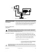

Table Of Contents
- Front Cover
- Contents
- List of Tables
- List of Figures
- Foreword
- Safety and General Information
- Introduction
- System Applications
- Models and Specifications
- Approved Accessories
- Setup and Connections
- Operation
- Troubleshooting
- Introduction
- Recommended Test Equipment
- Troubleshooting Procedures
- Module Replacement Procedures
- Preselector Field Tuning Procedure
- Functional Theory of Operation
- Schematics
- Back Cover
9-28 December 1, 2000 68P81093C75-O
If no preexisting codeplug is available, the new codeplug must
be configured manually using the RSS. See the Setup and
Connections section of this manual or the RSS User’s Guide
(68P81085E35) for details.
2. Perform the following alignment procedures as described in the
RSS User’s Guide (68P81085E35) or the Setup and
Connections section of this manual, or both.
• Reference Oscillator Calibration
• Squelch Adjust
• Power Output
• Tx Deviation Gain Adjust
• Reference Modulation
• RSSI Calibrate
For Wireline-equipped stations only:
• Tx Wireline
• Rx Wireline
For ASTRO stations only:
• Simulcast/ASTRO Launch Time Offset
For 6809 Trunking stations only:
• TDATA
Wireline
Physical Replacement of
the Wireline Module
1. Turn off the station’s power by unplugging the AC and DC
power cords from the top panel.
2. Remove the eight Phillips screws from the edges of the station’s
top panel and lift the chassis out of the case.
3. Remove the cover plate on the left end of the front of the station
by removing two Torx screws from the front of the plate.
Remove the four Phillips screws from the side and bottom
edges of the plate.
4. Pull out the old Wireline Module by gripping its front, right
corner (where there are no parts on the board).
5. Set all jumpers on the replacement board to match those on the
faulty board. These include the following:
• Input/ouput impedance matching jumpers