
User's Manual
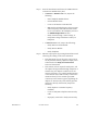
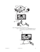


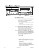
Table Of Contents
- Front Cover
- Contents
- List of Tables
- List of Figures
- Foreword
- Safety and General Information
- Introduction
- System Applications
- Models and Specifications
- Approved Accessories
- Setup and Connections
- Operation
- Troubleshooting
- Introduction
- Recommended Test Equipment
- Troubleshooting Procedures
- Module Replacement Procedures
- Preselector Field Tuning Procedure
- Functional Theory of Operation
- Schematics
- Back Cover

68P81093C75-O November 30, 2000 9-17
Step 4. If audio is heard, connect the HANDSET RJ-11 jack
to the Oscilloscope input BNC connector, as shown
below.
Figure 7 Test Equipment Setup for Verifying Receiver Circuitry
RF SECTION
MONITOR
OSCILLOSCOPE
COMMUNICATIONS
SYSTEM ANALYZER
1
0
23
456
789
Disconnect cables from top
panel transmit and
receive ports.
To
Antenna
RF In/Out
Motorola
R2001 Communications
Analyzer
Dummy
Load
PDR 3500
Top Panel
Connect UHF-to-N cable from station top panel
receive port to R2001 RF in/out. Connect UHF-to-N
cable from top panel transmit port to dummy load.
Connect handset to RJ-11 jack on
front panel of Station Control Module
(or External Speaker to RJ-11 jack).
3
2
1
MAEPF-27033-O
Handset
PTT
Button
RF SECTION
MONITOR
OSCILLOSCOPE
COMMUNICATIONS
SYSTEM ANALYZER
1
0
23
456
789
Oscilloscope
Input
MAEPF-27034-O
To
Station
Receive
Connector
Station Control
Module
Front Panel
RJ-11 to BNC Test Cable
Motorola Part No. 01-82069W01
(Available from Motorola WASPD)
Volume
Up Button