
User's Manual
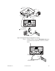


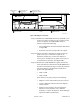
Table Of Contents
- Front Cover
- Contents
- List of Tables
- List of Figures
- Foreword
- Safety and General Information
- Introduction
- System Applications
- Models and Specifications
- Approved Accessories
- Setup and Connections
- Operation
- Troubleshooting
- Introduction
- Recommended Test Equipment
- Troubleshooting Procedures
- Module Replacement Procedures
- Preselector Field Tuning Procedure
- Functional Theory of Operation
- Schematics
- Back Cover
9-16 December 1, 2000 68P81093C75-O
Verifying Receiver
Circuitry Procedure
Step 1. Connect test equipment by performing Step 1 through
3 shown in Figure 7.
NOTE: The cover plate over the SCM side of the chassis
must be removed to perform these tests.
Step 2. Disable PL and carrier squelch by repeatedly pressing
the PL/CSQ/Off button until receiver noise is heard
through the handset (or external speaker). Refer to
Figure 5 for the location of the PL/CSQ/Off button. If
no audio is heard, suspect the following:
• Faulty Receiver Module
• Faulty Station Control Module
• R2001 is outputting a carrier signal
Step 3. Set R2001 to generate a 0.5 µV (-13 dBm) FM signal
at the PDR 3500 receiver frequency, modulated by a 1
kHz tone at 3 kHz deviation. The 1 kHz tone should be
audible through the handset (or external speaker). If
no audio is heard, suspect the following:
• Faulty Station Control Module (2.1 MHz
reference)
• Faulty Receiver Module
• Faulty antenna-to-Receiver preselector RF cable
• Faulty R2001-to-station RF cable
• Duplexer/station receive frequency mismatch, or
faulty duplexer