
User's Manual
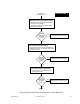
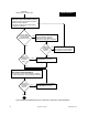

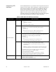


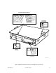
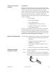
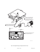
Table Of Contents
- Front Cover
- Contents
- List of Tables
- List of Figures
- Foreword
- Safety and General Information
- Introduction
- System Applications
- Models and Specifications
- Approved Accessories
- Setup and Connections
- Operation
- Troubleshooting
- Introduction
- Recommended Test Equipment
- Troubleshooting Procedures
- Module Replacement Procedures
- Preselector Field Tuning Procedure
- Functional Theory of Operation
- Schematics
- Back Cover

68P81093C75-O November 30, 2000 9-11
Verifying Transmitter
Circuitry
Introduction
While most module faults can be detected by running the station
diagnostics provided by the RSS, the following procedure provides
a more traditional method of troubleshooting the transmitter
circuitry. This procedure is useful in the event that the RSS is not at
hand or for some reason cannot be utilized (PC malfunction, etc.)
This procedure allows the service technician to make minor
adjustments and verify the proper operation of the station transmit
circuitry, including:
• Exciter Module
• Power Amplifier Module
• Power Supply Module
• 2.1 MHz Reference Oscillator Circuitry
• Transmitter-related circuitry on the Station
Control Module (SCM)
In general, the transmitter circuitry is exercised by injecting and
measuring signals using a Motorola R2001 Communications
Analyzer (or equivalent). Measured values outside the acceptable
range indicate a faulty module; values within range verify proper
operation of the above listed modules and circuitry.
Required Test Equipment The following test equipment is required to perform the procedure:
• Motorola R2001 Communications Analyzer (or
equivalent)
• Telephone-style handset with PTT switch
(TMN6164, or equivalent)
• In-line Wattmeter (Motorola Model S-1350, or
equivalent)
• Dummy Load (50Ω, station wattage or higher)
Verifying Transmitter
Circuitry Procedure
Step 1. Connect test equipment by performing Step 1 through
3 shown in Figure 6.
Step 2. Connect handset to RJ-11 connector on SCM front
panel, as shown. The cover plate over the SCM side of
the chassis must be removed to access this connector.
MEPF-27031-O
Handset
PTT
Button