
User's Manual
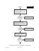
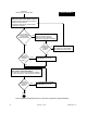

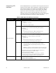


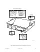
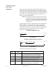
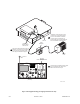
Table Of Contents
- Front Cover
- Contents
- List of Tables
- List of Figures
- Foreword
- Safety and General Information
- Introduction
- System Applications
- Models and Specifications
- Approved Accessories
- Setup and Connections
- Operation
- Troubleshooting
- Introduction
- Recommended Test Equipment
- Troubleshooting Procedures
- Module Replacement Procedures
- Preselector Field Tuning Procedure
- Functional Theory of Operation
- Schematics
- Back Cover

9-10 December 1, 2000 68P81093C75-O
Interpreting Alarm
Alert Tones
Introduction Four station alarm conditions are reported with audio alert tones
which are routed to the external speaker connector (RJ-11) on the
front of the control module. (Pin 4 on the RJ-11 is Speaker High; Pin
1 is Speaker Ground.) The alarms are also entered into the alarm log
which can be accessed using the RSS. Refer to the RSS User’s
Guide, part number 68P81085E35.
NOTE: The alarm tones may also be routed to the console
(via the wireline) and transmitted over the air. Refer
to the RSS User’s Guide (part number 68P81085E35)
for details on enabling or disabling these two alarm
routing options.
The four alarm conditions are represented by a series of alarm tones,
from a single beep, to four beeps. Each beep is a 1200 Hz tone,
lasting 125 msec. The alarm tones occur during a repeating 10
second window, with two seconds between successive alarms (when
more than one alarm is active). The following two examples
illustrate the timing of the alarm tones.
The alarm tone definitions are as follows:
Example 1: Single Alarm (#3)
beep...beep....beep.................................................................................................[repeats]
Alarm #3
10 Second Window
Example 2: Multiple Alarms (#1 and #4)
beep...........................beep....beep ... beep....beep................................................[repeats]
2 seconds
Alarm #1 Alarm #4
10 Second Window
Number of
Beeps
Alarm Condition
Name
Alarm Condition Description
1 Battery Revert Alarm is reported when station loses AC/DC line power and
reverts to battery backup. Alarm is cleared when station
receives AC/DC power. Should not occur in PDR 3500.
2 PA Fail Alarm is reported when PA fails to keyup to full ouput power.
Alarm is cleared upon successful keyup to full power.
3 Synthesizer Alarm is reported when either Tx or Rx synthesizers fail to
lock. Alarm is cleared when both sythesizers lock.
4 Overvoltage Alarm is reported when battery charging voltage is above
+34.5 V (100 W stations), or +17.25 V (20 W stations). Alarm
is cleared when voltage returns to normal range.