
User's Manual
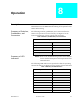
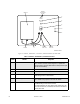
Table Of Contents
- Front Cover
- Contents
- List of Tables
- List of Figures
- Foreword
- Safety and General Information
- Introduction
- System Applications
- Models and Specifications
- Approved Accessories
- Setup and Connections
- Operation
- Troubleshooting
- Introduction
- Recommended Test Equipment
- Troubleshooting Procedures
- Module Replacement Procedures
- Preselector Field Tuning Procedure
- Functional Theory of Operation
- Schematics
- Back Cover

68P81093C75-O December 1, 2000 9-1
Troubleshooting 9
Introduction This section provides troubleshooting recommendations and
procedures for the PDR 3500 and associated ancillary equipment.
Troubleshooting
Overview
The troubleshooting procedures and supporting diagrams allow the
service technician to isolate station faults to the module/assembly
level, or to a limited portion of the motherboard circuitry.
The following information is included:
• Alarm indicators and their functions
• Troubleshooting flow charts
• Module replacement procedures
• Post-repair procedures: Performing alignment
after replacing defective modules
Recommended Test
Equipment
Follow this list of recommended test equipment when performing
troubleshooting procedures on the PDR 3500 and ancillary
equipment:
Test Equipment List • Motorola R2001 or R2600 Series
Communications Analyzer (or equivalent)
• PC with RSS program
• In-Line Wattmeter (Motorola S-1350, or
equivalent)
• Dummy Load (50Ω, station wattage or higher)
• Handset/Microphone with PTT switch
(TMN6164, or equivalent)
Troubleshooting
Procedures
The troubleshooting and repair philosophy employs Field
Replaceable Unit (FRU) substitution. The PDR 3500 is comprised of
self-contained modules (FRUs). Replacing faulty modules should
bring the station back to normal operation.