
User's Manual
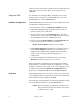
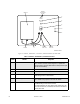
Table Of Contents
- Front Cover
- Contents
- List of Tables
- List of Figures
- Foreword
- Safety and General Information
- Introduction
- System Applications
- Models and Specifications
- Approved Accessories
- Setup and Connections
- Operation
- Troubleshooting
- Introduction
- Recommended Test Equipment
- Troubleshooting Procedures
- Module Replacement Procedures
- Preselector Field Tuning Procedure
- Functional Theory of Operation
- Schematics
- Back Cover

8-2 December 1, 2000 68P81093C75-O
Figure 2 . Switches , Pushbuttons , Connectors, and LED Indicators for PDR 3500
Table 7 Switches, Pushbuttons, and LED Indicators
Item Name Purpose
A EIA-232 RSS Port Connector Used to connect an IBM® PC (or compatible PC), running
RSS software. Performs station alignment, optimization,
and diagnostics. Requires Null Modem Cable (Motorola part
number 30-80369E31).
B DC Connector External DC source (+12 Vdc)
C AC Connector and Fuses AC Inlet (110/220 Vac, 3 A)
D Power/Transmit LED The function of this LED indicator is described in the Trou-
bleshooting section of this manual.
E Momentary PTT/Reset Switch When set to “PTT,” its purpose is to test the station. When
set to “RESET,” its purpose is to reset the station.
F Control Module Status LEDs The function of these LED indicators is described in the
Troubleshooting section of this manual.
The LED indicators are (from right to left): Station On; Sta-
tion Fail; Intcm/Acc D; Control Ch; Rx 1 Active; Rx2 Active;
Rx Fail; Aux LED.
Duplexer
Wireline
Connections
(RJ-45)
Antenna
Transmit
UHF Jack
Receive
UHF Jack
A
B
C
D
E
F
MAEPF-27065-O