
User's Manual


PMP320HDW2v1
2-19
Pr
e
limin
a
r
y
J
UL
2
0
1
0
PMP
320
Hardware
Installation
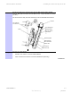
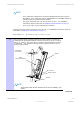
Attach
the
AP
assembly
to
a
pole
PWR
GND
1 3 5 7 9
11
2 4 6 8 1
0
12
13
1
4
POWER
DEFAULT
GPS_M
ETHERNET
PWR
ACTIVITY
LINK
SYNC
O
K
E
T
GPS
SWITCH
2
4
6 8
4 6 8
3
5 7
3 5 7
Procedure
2-3
Attaching
the
AP
assembly
to
a
pole
(Continued)
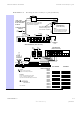
TOTAL
20
VDC
ACCESSORY
POWER
IS
NOT
TO
EXCEED
20
WATTS.
ACCESSORY
POWER
OUTPUTS
+20
V
+20
V
Twist
wire
pair
1
twist
per
inch
and
form
three
loops
around
ferrite
core
for
RF
emission
compliance.
Short
wire
to
ChassisGround
at
Switch
mounting
screw
for
RF
emission
compliance.
Green
Black
Red
EtherWAN
Switch
(
Power
Port
View
)
NOTE:
Refer
to
the
System
User
Guide
for
the
power
requirement
of
the
switch
OUTPUT
OUTPUT
specific
to
the
switch
part
number.
GND
(Black)
REDUNDANT
+V
(Red)
+29
V
REDUNDANT
+29
V
+56
V
+56
V
INPUT
INPUT
INPUT
INPUT
GND
GND
+V
GND
GND
+V
+V
GND
+V
GND
+V
GND
+V
GND
PE
CMM4
CONTROLLER
(
Power
Port
View
)
EXTERNAL
PROTECTIVE
EARTH
GROUND
+29
V
+56
V
EtherWAN
Switch
OUTPUT
Red
OUTPUT
Green
RS232
(
Ethernet
Port
View
)
OR
Red
Green
+29
V
+56
V
1000
BaseT
1000
BaseT
DEFAULT
NORMAL
OUTPUT
OUTPUT
AUX
SYNC
ETHERN
TOGGLE
SHIELDED
ETHERNET
CABLES
LEDs
N
Connector
INTERNAL
GPS
CABLE
CMM4
CONTROLLER
(
Ethernet
Port
View
)
MAC
ADDRESS
IP
ADDRESS
TO
GPS
ANTENNA
CAUTION:
Damage
my
result
if
non-approved
equipment
is
connected
to
powered
parts.
IMPORTANT
See
the
System
User
Guide
before
connecting
to
power.
The
Guide
is
available
on-line
at
http://motorola.wirelessbroadbandsupport.com/software/
www.motorola.com
P/N:
5487639D03
CMM4
CONTROLLER
PORT
1
PORT
2
PORT
3
PORT
4
PORT
5
PORT
6
PORT
7
PORT
8
PORT
9
PORT
10
PORT
11
PORT
12
PORT
13
PORT
14