
User's Manual


2-18
PMP320HDW2v1
Preliminary
JUL
2010
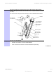
Attach
the
AP
assembly
to
a
pole
Chapter
2:
AP
Hardware
Installation
Procedure
2-3
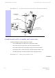
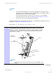
Attaching
the
AP
assembly
to
a
pole
(Continued)
2
Install
the
top
and
bottom
clamps
to
the
pipe.
Slide
the
clamp
bracket
on
to
the
carriage
bolts.
Slide
on
a
3/8-16
flat
washer
,
3/8-16
split
lock
washer
and
a
3/8-16
hex
nut
to
each
carriage
bolt.
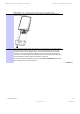
NOTE
•
Align
the
AP
setting
the
desired
downtilt
degree
using
the
inclinometer
.
•
The
network
planner
should
provide
the
antenna
pattern
information
for
the
installation.
The
network
is
planned
from
true
north
0
degrees.
Use
a
compass
to
ensure
there
is
no
overlap
of
the
antennas
as
they
are
installed.
Tighten
the
hex
nut
to
10
ft-lbs
(13.5
N
.m)
after
the
AP
has
been
aligned
to
the
optimum
downtilt
position.
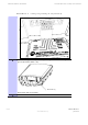
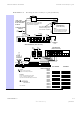
3
Connect
the
Ethernet
cable
from
the
AP
to
the
CMM4
port
controller
.
There
are
up
to
14
ports
in
one
CMM4
switch,
but
only
8
ports
on
the
CMM4
motherboard
that
can
power
up
a
radio
.
Ensure
that
surge
suppression
has
been
installed
for
this
connection.
See
the
section
on
Surge
Suppression
Information.
F
ollow
the
site
plan
created
by
the
network
planner
when
connecting
cables
to
the
CMM4
switch.
Continued