
User's Manual


PMP320HDW2v1
2-15
Pr
e
limin
a
r
y
J
UL
2
0
1
0
LED
indicator
Chapter
2:
AP
Hardware
Installation
LED
indicator
The
LED
display
for
the
AP
are
either
Green
or
off
.
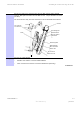
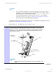
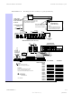
Figure
2-3
LED
location
diagram
Table
2-2
LED
indicators
for
the
AP
LED
Description
PWR
(D14)
P
ower
–
green
indicates
the
DC
power
is
on.
This
LED
indicates
that
the
board
is
powered
on.
SYN/1
(D13)
Synchronization
indicator
–
this
indicator
is
on
whenever
the
AP
is
synchronized
with
the
GPS
,
or
when
ever
the
GPS
is
not
used
at
all.
SES/2
(D12)
Not
used,
but
is
always
ON
.
LNK/5
(D9)
GMAC
Ethernet
–
the
LED
is
on
when
the
GMAC
Ethernet
link
is
up.
ACT/4
(D10)
Activity
–
indicates
activity
on
the
ENET
port.
GPS/3
(D11)
GPS
pulse
indicator
–
this
LED
is
on
every
1
pps
interrupt,
and
turned
off
20
frames
after
100
milliseconds).