
User's Manual


1-24
PMP320HDW2v1
Preliminary
JUL
2010
PMP
320
Hardware
Installation
Cluster
Management
Module
4
(CMM4)
•
Auto
-
negotiation
on
the
Ethernet
ports.
P
orts
will
auto
-
negotiate
to
match
inputs
that
are
either
100Base
-
T
or
10Base
-
T
,
and
either
full
duplex
or
half
duplex,
when
the
connected
device
is
set
to
auto
-
negotiate.
Alternativel
y
,
these
parameters
are
settable.
•
An
always
-
on
NTP
(Network
Time
Protocol)
server
that
can
provide
date
and
time
to
any
radio
that
can
reach
the
CMM’s
management
IP
address.
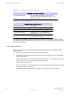
Table
1-4
CMM4
Model
Numbers
and
Ethernet
Switch
Configurations
CMM4
Model
CMM4
Extended
EtherW
AN
Switch
Number
Model
Number
T
otal
Ports
10/100
Base
–TX
Ports
10/100/1000
Base-TX
Ports
Cable
Glands
(ports)
1090CK
1090CKBA
(current
units)
1090CK
AA
(earlier
units)
14
12
2
7
9
8
1
4
1091
NA
No
Switch
7
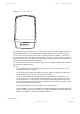
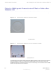
Inside
the
CMM4
enclosure
is
a
controller
board,
an
EtherWAN
switch,
and
a
GPS
coax
surge
suppressor
.
Also
inside
the
CMM4
enclosure
is
the
EtherWAN
switch
port.
This
connection
is
where
the
Ethernet
Gigabit
connection
is
made.
F
or
more
information
about
the
EtherWAN
switch
and
how
the
port
is
managed
or
for
information
on
earlier
versions
of
the
CMM4
units
refer
to
the
Cluster
Management
Module
4
User
Guide
located
at:
.
http://motorola.wirelessbroadbandsupport.com/
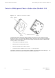
The
controller
board
injects
power
and
synchronization
on
up
to
eight
Ethernet
ports
and
provides
the
equivalent
of
600S
SD
surge
suppression
on
each
of
the
eight
ports.
The
controller
board
is
managed
using
a
web
browser
,
or
SNM
P
,
and
is
supported
by
the
Prizm
Element
Management
System
(EMS).
The
controller
board
receives
30
VDC
power
and/or
56
VDC
from
external
power
supplies,
and
provides
20
VDC
power
for
the
EtherWAN
switch
and
other
auxiliary
equipment.
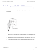
The
controller
board
includes
a
GPS
module,
which
provides
sync
and
GPS
information
to
the
CMM,
a
management
port,
an
override
toggle
switch,
and
an
auxiliary
sync
port
for
connecting
to
another
CMM.
NOTE
The
controller
board
does
not
convert
30
VDC
to
56
VDC
or
56
VDC
to
30
VDC
.
T
o
power
56
VDC
equipment
from
a
CMM4
you
must
provide
a
56
VDC
power
suppl
y
,
and
to
power
30
VDC
equipment
from
a
CMM4
you
must
provide
a
30
VDC
power
suppl
y
.
The
CMM4
requires
a
GPS
antenna
and
a
power
suppl
y
.
The
directions
for
installing
the
power
supply
and
the
GPS
are
provided
in
Chapter
3
CMM4
Hardware
Installation
.