
User's Manual


8-38
PMP320HDW2v1
Preliminary
JUL
2010
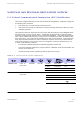
T
able
8
-
3
shows
calculated
minimum
separation
distances
d,
recommended
distances
and
resulting
power
compliance
margins
for
each
frequency
band
and
antenna
combination.
Details
of
Exposure
Separation
Distances
Calculations
and
Power
Compliance
Margins
Chapter
8:
Regulatory,
Legal,
and
Safety
Notices
Table
8-3
Calculated
exposure
distances
and
power
compliance
margins
P( dBm ) P( W ) G S Distance (cm ,
Calculated )
3630APC 25.1 0.324 16.5 10 33.92
3630SM 27.06 0.508 14.5 10 33.76
These
are
conservative
distances:
•
They
are
along
the
beam
direction
(the
direction
of
greatest
energy).
Exposure
to
the
sides
and
back
of
the
module
is
significantly
less.
•
In
the
case
of
collocated
AP
s,
they
assume
all
AP
s
are
oriented
in
the
same
direction,
which
is
a
worst
-
case
calculation.
•
They
meet
or
exceed
sustained
exposure
limits
for
the
general
population
(not
just
short
-
term
occupational
exposure
limits).
•
The
calculated
compliance
distance
d
is
overestimated
because
the
far
-
field
equation
models
the
antenna(s)
as
a
point
source
and
neglects
the
physical
dimension
of
the
antenna(s).
Table
8-4
Exposure
separation
distances
Module
T
ype
Separation
Distance
from
Persons
R
adio
Module
with
integrated
antenna
A
t
least
20
cm
(approximately
8
inches)
Module
with
Reflector
Dish
A
t
least
1.5
m
(approximately
60
inches
or
5
feet)
Module
with
LENS
A
t
least
0.5
m
(approximately
20
inches)
Antenna
of
connectorized
5.7
GHz
AP
A
t
least
30
cm
(approximately
12
inches)
Antenna
of
connectorized
or
integrated
900
MHz
module
A
t
least
60
cm
(approximately
24
inches)
Indoor
900
MHz
SM
A
t
least
10
cm
(approximately
4