
User's Manual


28
Two tests must be performed on the antenna to ensure that it meets the requirements. For both tests, the antenna must be
integrated in its final form. That is, the antenna must be mounted on a representative housing that includes all metal objects
forming the ground plane or counterpoise.
Antenna testing requires an experienced operator and an anechoic chamber, a GTEM cell, or approved open field site. Your
Motorola OEM support representative can provide advice on this type of testing.
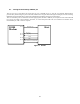
5.24. MECHANICS - MOUNTING IO200
5.25. Fastening Units into the terminal
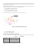
Mount Io200 modem to the terminal, using four M2-2a machine screws or substitute screws.
Figure 5. Mounting IO200 Modem (Iso View)
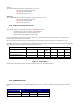
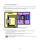
5.26. GPS CONSIDERATIONS
The IO200 includes an internal GPS receiver from Motorola.
The GPS receiver is powered internally from the IO200 unit with
2.775 V DC. All communication lines of the GPS are routed to the user 40 pin main connector through UART 2 as follows:
Table 6 The GPS Lines
IO200 User
Connector Pin #
Function
20 GPS RXD receives data in 3V logic.
19 GPS TXD transmits data in 3V logic.
More details about the GPS in the IO200 module can be viewed on the web.
4 screws M2