
User's Manual


19
5. DESIGN CONSIDERATIONS
5.1. GENERAL
When integrating a wireless modem, internal connections and placements are critical for a successful implementation.
Specific attention must be paid to the following support mechanisms:
• Power supply considerations
• Audio circuit considerations
• Data port considerations
• SIM card considerations
• ESD considerations
• Antenna considerations
• Mechanical mounting
• Desense control
• GPS considerations
Antennas must be separated by a minimum of 10 inches (25.4 cm).
Note
5.2. POWER SUPPLY CONSIDERATIONS
5.3. Power Supply Losses
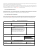
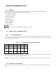
IO200 is specified to operate between 3.2V and 4.2V on the Main Connector. To enable operation with the lower battery
values, it is important to reduce the losses in the power supply lines. IO200 has to support iDEN training pulses of approximately
0.4 mS. The peak current is up to 3A.
Table 3 Module Input Voltage Specifications
Conditions Min.
Nom. Max. Unit
Input
Voltage
Standby/
Rx mode
3.2 4.0 4.2 V
Input
Voltage
At peak TX
current
3.0A
3.1 4.0 4.2 V
Ripple
In STBY
mode
50
mV
(peak)
In order to minimize ripple, noise and voltage loss it is recommended to use short and thick battery lines and to connect a low-
ESR, 1000 uF capacitor (or maximum possible) on the DC input.
In addition it is recommended to have a current limit in the power supply (3.5-5 A), in order to avoid damage if a short-circuit
occurs.
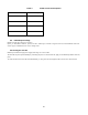
5.4. IO200 Current Consumption
In order to design the power supply correctly, you need to take into account the current consumption of IO200 in its different
modes.