
User's Manual

APPLICANT: MOTOROLA, INC. FCC ID: IHDT6AC1
Exhibit 8
18
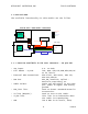
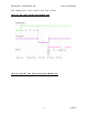
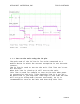
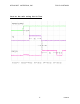
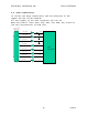
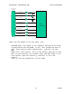
4.2 Data connectivity.
To clarify the Data connectivity and the direction of the
signal see the follow diagram:
All the signals in the user connector are 0 to 5V.
When the control lines (RTS, DTR, DCD, CTS, DSR, RI) active is
low (0V) and unactive is high (5V).
4
6
8
5
7
9
10
11
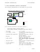
User connector
(ZIF 36 pin)
EXT_TXD
EXT_DTR
EXT_RTS
EXT_RXD
EXT_DCD
EXT_CTS
EXT_DSR
EXT_RI
TXD
DTR
RTS
RXD
DCD
CTS
DSR
RI
D15
processor