
User's Manual

APPLICANT: MOTOROLA, INC. FCC ID: IHDT6AC1
Exhibit 8
14
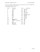
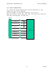
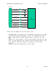
3.3.2 Connector pin out
Pin # Function Pin # Function
1. EXT. B+ (3.5 to 6V) 15. NU
2. EXT. B+ (3.5 to 6V) 16. TX_EN
3. SIM I/O 17. Analog GND
4. *SIM_RST 18. Audio Out+ On/Off
5. SIM VCC (3/5 Volt) 19. Audio In (Mic)
6. SIM PD 20. DSC_EN
7. DTR 21. DSR
8. TS 22. Down Link
9. Manual Test 23. Up Link
10. IRDA / RS232 Select 24. SIM_CLK
11. GND 25. TXD_U1
12. GND 26. RXD_U1
13. RI 27. CTS
14. DCD 28. RTS
Note:
1. The Audio Out line is used to send out the detected audio
and as a toggle On/Off pin.
2. The TS line is used to turn On the units by any transaction
from Low to high in this pin.
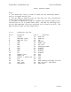
4. Modes of Operation
4.1 Turn On/Off the unit.
The D15 is powered from a single power supply in the range of
3.0 to 6.0 Vdc.
The unit will not power up automatically by connecting the
power and there are two ways to turn the unit On.
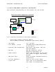
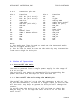
4.1.1 Turn On/Off the unit using the ON/OFF pin.
The On/Off pin (pin no’ 14 at the ZIF connector & pin no’ 18
at the DIN connector) is used as a toggel input to turn On and
Off the unit. Any drop to ground in this pin will change the
status.
To verify that the unit is On or Off you have to check the
DSC_EN line, If it is high the unit is On If it is low the
unit is Off.