
User's Manual
APPLICANT: MOTOROLA, INC. FCC ID: IHDT6AC1
Exhibit 8
12
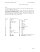
RTCM, Antenna power
Note:
1. The Audio Out line is used to send out the detected audio
and as a toggle On/Off pin.
2. The TS line is used to turn On the units by any transaction
from Low to high in this pin.
3. The GPS is mounted on top of theD15 and receive power from
the D15 but it is a stand-alone unit. The GPS is working from
3V and the RXD/TXD lines are working in 3V levels as well. The
GPS receiver used is M12 (Motorola).
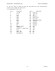
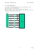
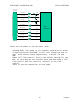
3.2.2 Connector pin out
Pin # Function Pin # Function
1 TX_EN 19 SIM I/O
2 GPS RXD (out) 20 SIM CLK
3 GPS TXD (in) 21 TS
4 TXD 22 DSC_EN
5 RXD 23 Down Link
6 DTR 24 Up Link
7 DCD 25 Analog Ground
8 RTS 26 Ground
9 CTS 27 Ground
10 DSR 28 Ground
11 RI 29 Ground
12 Manual_Test 30 VCC
13 Audio In 31 VCC
14 On/Off + Audio Out 32 VCC
15 N.U. 33 VCC
16 SIM _PD 34 GPS Antenna Voltage 3/5 Vdc
17 SIM _VCC 35 RX for diff. GPS RTCM
18 SIM_Reset 36 GPS 1pps