
User's Manual
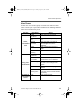
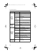


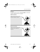
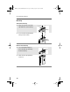

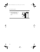
Table Of Contents
- Radio On/Off
- Zones/Channels
- Receive/Transmit
- Send Emergency Alarm
- Send Emergency Call
- Send Silent Emergency Alarm
- Display Status Symbols
- Menu Entries (Use With Menu Navigation)
- Contents
- Safety and General Information
- General Radio Operation
- Notations Used in This Manual
- Your XTS 5000 Model III Radio
- Physical Features of the XTS 5000 Model III Radio
- Programmable Controls
- Display
- Keypad
- LED Indicators
- Alert Tones
- Standard Accessories
- Radio On and Off
- Zones and Channels
- Receive / Transmit
- Common Radio Features
- Selectable Power Level
- Radio Lock
- Mute or Unmute Keypad Tones
- Conventional Squelch Operation
- PL Defeat
- Time-out Timer
- Emergency
- Lists
- Scan
- Individual Calls
- Status Calls (Trunked Radios Only)
- Repeater or Direct Operation
- Smart PTT (Conventional Only)
- Special Radio Features
- Helpful Tips
- Accessories
- Glossary
- Commercial Warranty
- Index
ASTRO Digital XTS 5000 Model III 19
General Radio Operation
Universal Connector Cover
The universal connector is located on the antenna side of the radio. It
is used to connect accessories to the radio.
Note: To prevent damage to the connector, shield it with the
connector cover when not in use.
Remove the Universal Connector Cover
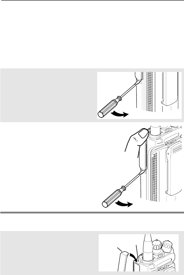
Attach the Universal Connector Cover
1 Insert a flat-blade
screwdriver into the area
between the bottom of the
cover and the slot below the
connector.
2 Hold the top of the cover with
your thumb while you pry the
bottom of the cover away
from the radio with the
screwdriver.
1 Insert the hooked end of the
cover into the slot above the
connector. Press downward
on the cover’s top to seat it in
the slot.
Top
Slot
Top
Hooked End
95C08-O_XTS5k_800MHz_Mdl3.book Page 19 Monday, August 27, 2001 9:09 AM