
User Manual
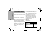

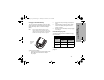
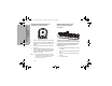
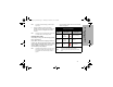
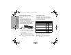
Table Of Contents
- Declaration of Conformity
- Computer Software Copyrights
- Radio Frequency (RF) Exposure Safety Standards
- FCC Licensing Information
- Introduction
- Radio Overview
- Battery and Charger Features
- Batteries and Chargers Safety Information
- Programming The Radio Through the CPS
- Radio Cloning
- Advanced Radio Configuration (*)
- Troubleshooting
- Use and Care
- Radio Frequency and Code Charts
- Motorola Solutions Limited Warranty for the United States and Canada
- Untitled
- Accessories

17
BATTERY AND CHARGER
FEATURES
Note: If the radio is ON while charging, it takes longer to
fully charge.
5. Insert the radio facing down (with battery
installed) into the charging pocket, making sure
the radio contacts are aligned with the MUC
contacts.
Note: The battery can be charged by itself using the slot
on the flat surface of the charging pocket.
Charging Status LEDs
On the drop-in charger, the radio charging pocket
has an LED Charger.
On the MUC, each of the 6 charging pockets has
an LED. The LEDs are grouped into pairs to show
which charging pockets are paired. The LED is red
when the battery is charging. It turns to green
once the battery is fully charged.
Note: This Multi Unit Charger allows you to clone up to 2
radios (2 Source radios and 2 Target radios). For
more details, refer to “Radio Cloning” Section on
page 24.
• For part number details, refer to the“Accessories”
Section on page 43.
Charger LED Indicator
Status LED Status Comments
Charging Steady
Red
Indication
The charger is
currently charging.
Charge
Complete
Steady
Green
Indication
Battery is fully
charged.
Battery
Fault (*)
Blinking
Red
Battery was faulty
when inserted.
Note: The LED is red when the battery is charging. It turns
to green once the battery is fully charged.
Note: (*) Re-seating the battery pack likely corrects this
issue.
2000044_CLP_en.book Page 17 Thursday, November 9, 2017 6:40 PM