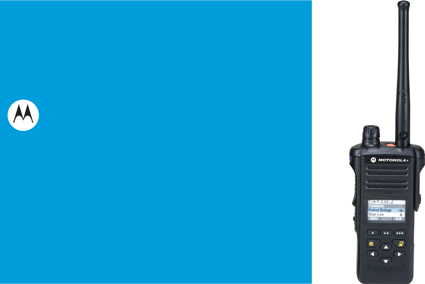
m ASTRO® APX 4000 Series Digital Portable Radios Quick Reference Card Top Lightbar Microphone Product Safety and RF Exposure Compliance Before using this product, read the operating instructions for safe usage contained in the Product Safety and RF Exposure booklet enclosed with your radio. ATTENTION! This radio is restricted to occupational use only to satisfy FCC RF energy exposure requirements.
Sending an Emergency Call 1 Press the Emergency button. 2 Press and hold the PTT button. Speak clearly 8 V Blinks when the battery is low. O Direct radio to radio communication or connected through a repeater. On = Direct Off = Repeater into the microphone. 3 Release the PTT button to end call. 4 Press and hold Emergency button to exit emergency. To exit emergency at any time, press and hold the Emergency button.
Declaration of Conformity This declaration is applicable to your radio only if your radio is labeled with the FCC logo shown below. DECLARATION OF CONFORMITY Per FCC CFR 47 Part 2 Section 2.1077(a) Responsible Party Name: Motorola Solutions, Inc. Address: 1303 East Algonquin Road, Schaumburg, Illinois 60196, U.S.A. Phone Number: 1-800-927-2744 Hereby declares that the product: Model Name: APX 4000 conforms to the following regulations: FCC Part 15, subpart B, section 15.107(a), 15.107(d) and section 15.
Note: This equipment has been tested and found to comply with the limits for a Class B digital device, pursuant to part 15 of the FCC Rules. These limits are designed to provide reasonable protection against harmful interference in a residential installation. This equipment generates, uses and can radiate radio frequency energy and, if not installed and used in accordance with the instructions, may cause harmful interference to radio communications.
Contents This User Guide contains all the information you need to use the APX 4000 Series Digital Portable Radios. Declaration of Conformity . . . . . . . . . . . . . . . . .i Important Safety Information . . . . . . . . . . . . . .ix Product Safety and RF Exposure Compliance . . . . .ix Software Version . . . . . . . . . . . . . . . . . . . . . . . .ix Disclaimer . . . . . . . . . . . . . . . . . . . . . . . . . . . . . xi Getting Started . . . . . . . . . . . . . . . . . . . . . . . . . .
Identifying Radio Controls . . . . . . . . . . . . . . . . .9 Alert Tones . . . . . . . . . . . . . . . . . . . . . . . . . . . . . . . 25 Radio Parts and Controls . . . . . . . . . . . . . . . . . . . . 10 Phone Call Display and Alert Prompts . . . . . . . . . . 29 Programmable Features . . . . . . . . . . . . . . . . . . . . . 11 Assignable Radio Functions . . . . . . . . . . . . . . . . . . 11 Assignable Settings or Utility Functions . . . . . . . . . 13 Contents Selecting a Zone . . . . . . . . .
Advanced Features . . . . . . . . . . . . . . . . . . . . . 42 Advanced Call Features . . . . . . . . . . . . . . . . . . . . . 42 Receiving and Making a Selective Call (ASTRO Conventional Only) . . . . . . . . . . . . . . . . . . . . . . . . .42 Receiving a Selective Call . . . . . . . . . . . . . . . . . . . 42 Making a Selective Call . . . . . . . . . . . . . . . . . . . . . 43 Using the Talkgroup Call Feature (Conventional Operation Only) . . . . . . . . . . . . . . . . . . . . . . . . . . . .
Contents Text Messaging Service (TMS) . . . . . . . . . . . . . . . 63 Accessing the TMS Features . . . . . . . . . . . . . . . . . 64 Sending a Quick Text Message . . . . . . . . . . . . . . . 64 Using the Priority Status and Request Reply Features . . . . . . . . . . . . . . . . . . . . . . . . . . . . . . . . . 65 Appending a Priority Status to a Text Message . . . 65 Removing a Priority Status from a Text Message . 66 Appending a Request Reply to a Text Message . .
Mission Critical Wireless - Bluetooth® - . . . . . . . . . . . . . . . . . . . . . . . . . . . . 84 Turning the Bluetooth On . . . . . . . . . . . . . . . . . . . .85 Turning the Bluetooth Off . . . . . . . . . . . . . . . . . . . .85 Re-Pair Timer . . . . . . . . . . . . . . . . . . . . . . . . . . . . .86 Bluetooth Drop Timer . . . . . . . . . . . . . . . . . . . . . . .87 Pairing Bluetooth Device with the Radio . . . . . . . . .87 Indicating Bluetooth Connection is Lost . . . . . . . . .
Taking Care of the Battery . . . . . . . . . . . . . . . . . . 110 Checking the Battery Charge Status . . . . . . . . . . 110 LED and Sounds . . . . . . . . . . . . . . . . . . . . . . . . . 110 Fuel Gauge Icon . . . . . . . . . . . . . . . . . . . . . . . . . 110 Battery Recycling and Disposal . . . . . . . . . . . . . . 111 Appendix: Maritime Radio Use in the VHF Frequency Range . . . . . . . . . . . . . . . . . . . . . 113 Special Channel Assignments . . . . . . . . . . . . . . . 113 Emergency Channel .
Important Safety Information Software Version Product Safety and RF Exposure Compliance All the features described in the following sections are supported by the radio's software version R07.00.00 or later. Before using this product, read the operating instructions for safe usage contained in the Product Safety and RF Exposure booklet enclosed with your radio. ATTENTION! This radio is restricted to occupational use only to satisfy FCC RF energy exposure requirements.
Informations importantes sur la sécurité x Informations importantes sur la sécurité Sécurité du produit et respect des lignes directrices concernant l'exposition à l'énergie RF Avant d'utiliser ce produit, lisez les directives d'utilisation sécuritaire présentées dans le livret Sécurité du produit et exposition à l'énergie RF accompagnant votre radio. ATTENTION! Cette radio est réservée à un usage professionnel seulement pour satisfaire les normes d'exposition à l'énergie RF de la FCC.
Computer Software Copyrights Documentation Copyrights The Motorola products described in this manual may include copyrighted Motorola computer programs stored in semiconductor memories or other media. Laws in the United States and other countries preserve for Motorola certain exclusive rights for copyrighted computer programs, including, but not limited to, the exclusive right to copy or reproduce in any form the copyrighted computer program.
Disclaimer Notes xii English
Getting Started Take a moment to review the following: How to Use This Guide . . . . . . . . . . . . . . . . . . . . . . . . . page 1 Notations Used in This Manual . . . . . . . . . . . . . . . . . . . page 1 Additional Performance Enhancement . . . . . . . . . . . . . page 2 What Your Dealer/System Administrator Can Tell You. . . . . . . . . . . . . . . . . . . . . . . . . . . . . . . .
The following special notations identify certain items: Example Description Home button Buttons and keys are shown in bold print or H or as an icon. Phone Getting Started > 2 English Menu entries are shown similar to the way they appear on your radios display. This means Press the right side of the 4-way Navigation button. Additional Performance Enhancement The following are some of the latest creations designed to enhance the security, quality and efficiency of your radio.
CrossTalk Prevention This feature prevents crosstalk scenario from happening, especially when a wideband antenna is used. This feature allows the adjustment of the Trident Transmitting SSI clock rate in your radio to be varied from the Receiving Frequency. This subsequently reduced the possibilities of radio frequency interfering spurs and prevents the issues of crosstalk.
Charging the Battery Preparing Your Radio for Use Preparing Your Radio for Use Assemble your radio by following these steps: Charging the Battery . . . . . . . . . . . . . . . . . . . . . . . . . . . Battery Charger . . . . . . . . . . . . . . . . . . . . . . . . . . . . . Attaching the Battery. . . . . . . . . . . . . . . . . . . . . . . . . . . Attaching the Antenna. . . . . . . . . . . . . . . . . . . . . . . . . . Attaching the Accessory Connector Cover . . . . . . . . . . Attaching the Belt Clip. .
Attaching the Battery To remove the battery, turn the radio off. Lift up the latch then slide the battery down to remove the battery from the radio. With the radio turned off, slide the battery into the radios frame until the bottom latch clicks into place. Battery Latch is at the bottom of the battery. Note: If your radio is preprogrammed with volatile-key retention, the encryption keys are retained for approximately 30 seconds after battery removal.
Attaching the Antenna With the radio turned off, set the antenna in its receptacle and turn clockwise to attach it to the radio. Attaching the Accessory Connector Cover The accessory connector is located on the antenna side of the radio. It is used to connect accessories to the radio. Preparing Your Radio for Use Note: To prevent damage to the connector, shield it with the connector cover when not in use. Insert the hooked end of the cover into the slot above the connector.
Attaching the Belt Clip Align the grooves of the belt clip with those of the radio and press upward until you hear a click. Turning On the Radio Press and hold the Multi-Function Knob (MFK) until the radio display lights up, then release the MFK. Tab To remove the clip, use a flatbladed object to press the belt clip tab away from the radio. Then, slide the clip downward and away from your radio. If the power-up test is successful, you see the Home screen.
Note: If the power-up test is successful, but you see Hardware board absent or Hw Board Mismatch. Then, send your radio to the qualified technician to fix this error. Preparing Your Radio for Use If the power-up test is successful, but you see, Hw Board Failed or Man-Down Hw Error, send your radio to the qualified technician to fix this error. Adjusting the Volume To increase the volume, turn the MFK clockwise. The display shows volume bars and volume level when you change the volume.
Identifying Radio Controls Take a moment to review the following: Radio Parts and Controls . . . . . . . . . . . . . . . . . . . . . . page 10 Programmable Features . . . . . . . . . . . . . . . . . . . . . . . page 11 Assignable Radio Functions . . . . . . . . . . . . . . . . . . page 11 Assignable Settings or Utility Functions. . . . . . . . . . page 13 Accessing the Preprogrammed Functions. . . . . . . . . . page 13 Using the Menu Select Buttons . . . . . . . . . . . . . . . .
Radio Parts and Controls 1 Top (Orange) Button* 16 Antenna 2 Top Lightbar 15 LED 21 Identifying Radio Controls 3 Microphone 4 Top Side (Select) Button* 5 Push-to-Talk (PTT) Button 14 Bluetooth® Pairing Indicator 20 Microphone 13 Speaker 17 Accessory 12 Main Display 6 Side Button 1* MultiFunction Knob (MFK)* Connector 19 Battery 11 Menu Select Buttons 7 Side Button 2* 10 Data Feature Button 8 10 English Home Button 9 4-Way Navigation Button Battery 18 Latch (at the bottom) * These r
Programmable Features Bluetooth Headset and PTT Keys up the Bluetooth Headset's microphone. Any reference in this manual to a control that is preprogrammed means that the control must be programmed by a dealer or qualified radio technician using the radio's programming software, in order to assign a feature to that control. Bluetooth Data Devices Keys up the Bluetooth data devices.
Location Determines the current location (latitude, longitude, time and date), and also the distance and bearing to another location. Or, turns the GPS functionality on or off for all location. Man Down Clear Clears the alarm of Man Down mode which was triggered when the radio achieves or passes a tilt angle threshold or a combination of the angle threshold and a motion sensitivity level. Identifying Radio Controls Message Enters the current message list.
Site Lock/Unlock (Trunking Only) Locks onto a specific site. Status Sends data calls to the dispatcher about a predefined status. Talkaround/Direct (Conventional Only) Toggles between using a repeater and communicating directly with another radio. Talkgroup (Conventional Only) Allows a call from an individual radio to a group of radios. Text Messaging Service (TMS) Selects the text messaging menu.
Using the Menu Select Buttons Using the Navigation Buttons The Menu Select buttons access the menu entries of features. Note: Check with your dealer or system administrator for the list of features activated in your radio. Your radio may be preprogrammed differently from the following example, but the steps for selecting a channel may appear as shown below: Identifying Radio Controls Press the Menu Select button ( | ) directly below Chan.
Data Feature Button Use this button to access data-related features, such as the Text Messaging Service (TMS) feature screen. 4-Way Navigation Button Use this button to scroll up, down, left or right. Press and release one of the button to scroll from one entry to the next one. Press and hold one of the button to have your radio toggles through the list automatically (release the button to stop). Multi-Function Knob (MFK) MFK is the on/off button of your radio.
Push-To-Talk (PTT) Button The PTT button on the side of the radio serves two basic purposes : Your radio indicates its operational status through the following: While a call is in progress, Identifying Status Indicators the PTT button allows your radio to transmit to other radios in the call. Press and hold down PTT button to talk. Release the PTT button to listen. The microphone is activated when the PTT button is pressed. Identifying Status Indicators PTT Button Status Icons . . . . . . . . . . .
The following icons are for the front display screen unless indicated otherwise. Receiving Radio is receiving a call or data. O Direct On = Radio is currently configured for direct radio-to-radio communication (during conventional operation only). Off = Radio is connected with other radios Transmitting Radio is transmitting a call or data. Battery For IMPRES battery operation only the icon shown indicates the charge remaining in the battery.
Priority Channel Scan Blinking dot = Radio detects activity on channel designated as Priority-One. Location Signal G Blinking = Location feature is enabled, but no Identifying Status Indicators designated as Priority-Two. location signal is available. Vote Scan Enabled The vote scan feature is enabled. Secure Operation User Login Indicator (IP Packet Data) n On = Secure operation.
Bluetooth Connected Bluetooth is currently connected to the external bluetooth device. MFK is in Mode Change feature Turn the MFK to change the channel/zone. MFK is in Volume Change feature Turn the MFK to turn the volume up or down. Text Messaging Service (TMS) Icons This feature allows you to send and receive text messages. See Text Messaging Service (TMS) on page 63 for more information. Status Icons The following icons appear on your radios display when you send and receive text messages.
Request Reply r Normal Message User is composing a message with normal priority and without a request for a reply. Messages in the Inbox folder are flagged with 3/6 Message Index Indicates the index of the current message the user is viewing. Example: If the user is looking at the third message out of a total of 6 messages in the Inbox folder, the icon is displayed as the icon on the left column. Identifying Status Indicators Y Read Message The selected text message in the Inbox has been read.
Call Type Icons TMS Menu Options Menu Option Back Description/Function Brings you back to the previous screen. Clr Deletes all messages. Del Deletes a message. Exit Exits to the Home screen. No Returns to the previous screen. Optn Brings you to the Options main screen. Rply Replies to a message. Sel Send Yes Selects the highlighted command. Sends the message. Updates or saves a command.
% Top Lightbar and LED Indicators Landline phone number. The Top Lightbar and LED indicators show the operational status of the radio. Landline phone number added to a Call List. LED Identifying Status Indicators Incoming call or data. 22 English Outgoing call or data. Incoming emergency call.
LED Indications Solid red Radio is transmitting. Blinking red Radio is transmitting at low battery condition. Rapidly blinking red Radio has failed the self test upon powering up or encountered a fatal error. Solid yellow (Conventional Only) Channel is busy. Blinking yellow Radio is receiving a secured transmission. Top Lightbar Indications The lightbar blinks green when the MFK is using the secondary feature. See Multi-Function Knob (MFK) on page 15 to understand the functionality of MFK.
Intelligent Lighting Indicators This feature temporary changes the color of the Top Lightbar and adds a color bar to the main display screen to help signal that a radio event has occurred. Identifying Status Indicators Note: 24 English This feature must be preprogrammed by a qualified radio technician. Bar Color Notification Orange Emergency Alerts When The radio initiates an emergency alarm or call. The radio receives an emergency alarm or call. The radio battery is low. The radio is out of range.
Alert Tones The radio uses alert tones to inform you of the radios condition. The following table lists these tones and when they occur. You Hear Tone Name Radio Self Test Fail Reject Short, Low-Pitched Tone Long, Low-Pitched Tone A Group of Low-Pitched Tones Time-Out Timer Warning No ACK Received Individual Call Warning Tone Heard When radio fails its power-up self test. When an unauthorized request is made. Four seconds before time out. When radio fails to receive an acknowledgment.
You Hear Tone Name Valid Key-Press Radio Self Test Pass Identifying Status Indicators Short, Medium-Pitched Tone Clear Voice Priority Channel Received Emergency Alarm /Call Entry Central Echo Long, Medium-Pitched Tone Volume Set Emergency Exit Failsoft Automatic Call Back Talk Permit A Group of Medium-Pitched Tones 26 English Keyfail Console Acknowledge Received Individual Call Heard When a correct key is pressed. When radio passes its power-up self test. At beginning of a non-coded communication.
You Hear Tone Name Short, High-Pitched Tone (Chirp) Low-Battery Chirp Fast Ringing Ringing Heard When battery is below preset threshold value. When system is searching for target of Private Call. Enhanced Call Sent When waiting for target of Private Call to answer the call. Phone Call Received When a land-to-mobile phone call is received. Gurgle Dynamic Regrouping (When the PTT button is pressed) a dynamic ID has been received.
You Hear Tone Name IncrementalPitched Tone Bluetooth Paired Identifying Status Indicators DecrementalPitched Tone A Group of Very High-Pitched Tones 28 English Heard When Bluetooth accessory is paired with the radio. Bluetooth Connected When Bluetooth accessory is connected to the radio. Bluetooth Unpaired When Bluetooth accessory is unpaired from the radio. Bluetooth Disconnected When Bluetooth accessory is disconnected from the radio.
Phone Call Display and Alert Prompts The following appears on the radios display when you make and receive Phone calls. The radio also uses alert tones to indicate the current status. You Hear You See When A Long Tone No phone You press the PTT button and the phone system is not available. Press H to hang up. The radio returns to the Home screen. Phone busy The phone system is busy. Press H to exit the phone mode and try your call later. Phone busy When a channel is not available.
Selecting a Zone General Radio Operation A zone is a group of channels. Once you understand how your APX 4000 Portable is configured, you are ready to use your radio. General Radio Operation Use this navigation guide to familiarize yourself with the basic Call features: Selecting a Zone . . . . . . . . . . . . . . . . . . . . . . . . . . . . . Selecting a Radio Channel . . . . . . . . . . . . . . . . . . . . . Receiving and Responding to a Radio Call. . . . . . . . . Making a Radio Call . . . . . . . .
Procedure: Turn the preprogrammed Zone Change MFK to the required zone and proceed to Step 3. OR Follow the procedure below. Selecting a Radio Channel A channel is a group of radio characteristics, such as transmit/ receive frequency pairs. 1 < or > to Zone. MFK 2 Press the Menu Select button directly below Zone. 3 U or D to the required zone. 4 Press the Menu Select button directly below Sel to confirm the displayed zone. 5 Press the PTT button to transmit on the displayed zone channel.
General Radio Operation If Mode Change is secondary feature of MFK, see Multi-Function Knob (MFK) on page 15 to toggle the function of MFK. Using Mode Select Feature Procedure: Turn the preprogrammed MFK to the desired channel. OR Follow the procedure below. Mode Select allows a long press to save the radios current zone and channel to a programmable button, keypad button or a softkey; then once programmed, the short-press of that button or softkey jumps the transmission to the saved zone and channel.
Saving a Zone and Channel to a Softkey Saving a Zone and Channel to a Button Five softkeys are available for you to save the frequent used zone and channel. All the programmable buttons and keypad digit 0 to 9 buttons allow you to save the frequent used zone and channel. Procedure: Procedure: 1 Toggle your zone and channel to the required zone and 1 Toggle your zone and channel to the required zone and channel. channel. 2 < or > to MS1, MS2 ... or MS5.
Receiving and Responding to a Radio Call Once you have selected the required channel and/or zone, you can proceed to receive and respond to calls. LED Indicator Receiving and Responding to a Talkgroup Call To receive a call from a group of users, the radio must be configured as part of that talkgroup. Procedure: When you receive a talkgroup call (while on the Home screen), depending on how your radio is preprogrammed: General Radio Operation 1 ASTRO Conventional Only: The LED lights up solid yellow.
Receiving and Responding to a Private Call (Trunking Only) A Private Call is a call from an individual radio to another individual radio. These one-to-one calls between two radios are not heard by others in the current talkgroup. The calling radio automatically verifies that the receiving radio is active on the system and can display the caller ID. Note: The radio automatically exits the feature, if the feature inactivity timer is enabled, when the radio is left idle and the timer expires.
Procedure: Use the preprogrammed Call Response button to answer a Telephone Call: 1 You hear a telephone-type ringing and the LED blinks green. The backlight of the screen and the bar turns green. The display shows Phone Call and the call received icon blinks. 2 Press the Call Response button within 20 seconds after the call indicators begin. 3 Press and hold the PTT button to talk. Release the PTT General Radio Operation button to listen.
3 Press the PTT button to make the call. 4 ASTRO Conventional Only: The LED lights up solid red. The display shows the talkgroup alias or ID. OR Trunking Only: The LED lights up solid red. 3 Press the Menu Select button directly below Cnts to scroll through and select the required ID. OR Press the Menu Select button directly below LNum to go to the last number dialed. OR U or D to the required ID. 5 Speak clearly into the microphone. 4 Press the PTT button to start the Private Call.
Making an Enhanced Private Call (Trunking Only) This feature allows you to send an individual Call Alert page if there is no answer from the target radio. See Sending a Call Alert Page on page 53 for more information. General Radio Operation Note: Your radio must be preprogrammed to allow you to use this feature. Procedure: Press the preprogrammed Quick Access (One-Touch) Enhanced Private Call button to dial the preprogrammed ID and proceed to Step 5. OR Follow the procedure below. 1 < or > to Call.
Making a Telephone Call (Trunking Only) 4 Press and release the PTT button to dial the phone number. This feature allows you to make calls similar to standard phone calls to a mobile or landline phone. 5 Hold the radio vertically 1 to 2 inches (2.5 to 5.0 cm) from Procedure: Press the preprogrammed Quick Access (One-Touch) Phone Call button to dial the preprogrammed phone number and proceed to Step 5. OR Follow the procedure below. 6 When your call is answered, press the PTT button to talk.
Repeater or Direct Operation The REPEATER operation increases the radios range by connecting with other radios through a repeater. The transmit and receive frequencies are different. General Radio Operation The DIRECT or talkaround operation allows you to bypass the repeater and connect directly to another radio. The transmit and receive frequencies are the same. Procedure: Press the preprogrammed Repeater/Direct button to toggle between talkaround and repeater modes. OR Follow the procedure below.
Monitoring a Channel Procedure: Press the preprogrammed Monitor button and proceed to Step 3. OR Follow the procedure below. 1 Select the desired zone and channel. 2 Listen for a transmission. 3 Adjust the Volume Change MFK if necessary. 4 Press and hold the PTT button to transmit. The LED lights Conventional Mode Operation Your radio may be preprogrammed to receive Private-Line® (PL) calls. Procedure: 1 Momentarily press the Monitor button to listen for activity.
Advanced Features Advanced Features Use this navigation guide to learn more about advanced features available with your radio: Advanced Call Features . . . . . . . . . . . . . . . . . . . . . . . page 42 Contacts . . . . . . . . . . . . . . . . . . . . . . . . . . . . . . . . . . . page 46 Scan Lists . . . . . . . . . . . . . . . . . . . . . . . . . . . . . . . . . . page 49 Scan . . . . . . . . . . . . . . . . . . . . . . . . . . . . . . . . . . . . . . page 51 Call Alert Paging . . . . . . . . . . . . .
Making a Selective Call Procedure: Press the preprogrammed Quick Access (One-Touch) Selective Call button to dial the preprogrammed ID and proceed to Step 4. OR Follow the procedure below. 1 < or > to Call. 2 Press the Menu Select button directly below Call. The display shows the last transmitted or received ID. 3 Press the Menu Select button directly below Cnts to scroll through and select the required ID. OR Press the Menu Select button directly below LNum to go to the last number dialed.
3 U or D to Preset for the preset preprogrammed talkgroup. OR U or D to the required talkgroup. 4 Press the Menu Select button directly below Sel to save the currently selected talkgroup and return to the Home screen. 5 If the encryption key associated to the new talkgroup is erased, you hear a momentary key fail tone and the display shows Key fail. OR If the encryption key that is associated to the new talkgroup is not allowed, you hear a momentary key fail tone and the display shows Illegal key.
Using the Dynamic Regrouping Feature (Trunking Only) This feature allows the dispatcher to temporarily reassign selected radios to a particular channel where they can communicate with each other. This feature is typically used during special operations and is enabled by a qualified radio technician. You will not notice whether your radio has this feature enabled until a dynamic regrouping command is sent by the dispatcher.
Classifying Regrouped Radios The dispatcher can classify regrouped radios into either of two categories: Select Enabled or Select Disabled. Select-enabled radios are free to change to any available channel, including the dynamic-regrouping channel, once the user has selected the dynamic-regrouping position. Select-disabled radios cannot change channels while dynamically regrouped. The dispatcher has forced the radio to remain on the dynamic-regrouping channel.
Your radio also supports a maximum of 50 call lists. Each list can store up to 100 IDs (numbers). Note: Your radio is preprogrammed with a number of contacts per Call Lists. Check with your dealer or system administrator for more information. The radio automatically exits the feature, if the feature inactivity timer is enabled, when the radio is left idle and the timer expires. You will hear the Menu Inactive Exit Tone upon feature exit.
Adding a Contact to a Call List Procedure: Procedure: 1 < or > to Cnts. 1 < or > to Cnts. 2 Press the Menu Select button directly below Cnts. The 2 Press the Menu Select button directly below Cnts. The entries are alphabetically sorted. 3 U or D to the entry you want to add to a call list and press the Menu Select button directly below Optn. 4 U or D to Add to CallLst and press the Menu Select button directly below Sel.
Scan Lists Scan lists are created and assigned to individual channels/ groups. Your radio scans for voice activity by cycling through the channel/group sequence specified in the scan list for the current channel/group. Your radio supports different types of Scan Lists: Trunking Priority Monitor Scan List Conventional Scan List Talkgroup Scan List Please refer to a qualified radio technician for the maximum number of Scan Lists can be programmed in your radio.
6 Press H to exit scan list programming and return to the Home screen. See Viewing and Changing the Priority Status on page 50 for more information on how to add and/or change the priority of the currently displayed channel in the scan list. Changing the Scan List Status Procedure: 1 Long press the preprogrammed Scan List Programming button (side button). 2 The display shows the programming mode icon and the first Advanced Features list member. 3 U or D to the member you want to edit.
Scan This feature allows you to monitor traffic on different channels by scanning a preprogrammed list of channels. Turning Scan On or Off Procedure: Press the preprogrammed Scan button to start or stop scan. OR Follow the procedure below. 1 < or > to Scan. 2 Press the Menu Select button directly below Scan. 3 The display shows Scan off if scan is disabled. Press the Menu Select button directly below Scan to enable scan. OR The display shows Scan on and the scan status icon if scan is enabled.
2 The radio continues scanning the remaining channels in the Call Alert Paging list. This feature allows your radio to work like a pager. Restoring a Nuisance Channel Procedure: To restore the deleted nuisance channel, do one of the following: Turn the radio off and then turning it on again. OR Stop and restart a scan via the preprogrammed Scan button or menu. Advanced Features OR Change the channel via the MFK.
Sending a Call Alert Page Note: The radio automatically exits the feature, if the feature inactivity timer is enabled, when the radio is left idle and the timer expires. You will hear the Menu Inactive Exit Tone upon feature exit. 6 If the call alert page is sent successfully, you hear a tone and the display shows Ack received. OR If the call alert page is not acknowledged, you hear a low tone and the display shows No acknowledge. 7 The radio returns to the Home screen.
5 Press the Menu Select button directly below Yes to send the call alert page. OR Press the Menu Select button directly below No to exit the screen without sending the call alert page. The Emergency feature is used to indicate a critical situation. 6 The display shows Paging... . If the Top (Orange) button is preprogrammed to send an emergency signal, this signal overrides any other communication over the selected channel.
Sending an Emergency Alarm This feature allows you to send a data transmission, which identifies the radio sending the emergency, to the dispatcher. Note: Emergency button press timer by default is set to 1 second. This timer is programmable from 0 6 seconds by a qualified technician. Procedure: 1 Press the preprogrammed Emergency button. 2 The display shows Emergency and the current zone or channel. You hear a short, medium-pitched tone and the LED momentarily blinks red.
5 Release the PTT button to end the transmission and wait for a response from the dispatcher. 6 Press and hold the preprogrammed Emergency button for about a second to exit the Emergency Call mode. 4 Hold the radio vertically 1 to 2 inches (2.5 to 5.0 cm) from your mouth. 5 Press and hold the PTT button. Speak clearly into the microphone. 6 Release the PTT button to end the transmission and wait for Sending an Emergency Alarm with Emergency Call Procedure: a response from the dispatcher.
Note: For ALL Emergency signals, when changing channels: Man Down If the new channel is also preprogrammed for Emergency, you can change channels while in Emergency operation. The emergency alarm or call continues on the new channel. If the new channel is NOT preprogrammed for Emergency, the display shows No emergency, and you hear an invalid tone until you exit the Emergency state or change to a channel preprogrammed for Emergency.
The Man Down feature has three phases: i ii iii The radio senses the Man Down condition and Pre-Alert Timer is initiated. Man Down condition continues for the time duration defined in the Pre-Alert Timer field. At the end of this time, the radio alerts the user on the Man Down status with an audible alert tone and Man Down text on the screen. The Post-Alert Timer also initiates at this point. Man Down condition continues for the time duration defined in the Post-Alert Timer field.
Post-Alert Timer This timer sets the amount of time the radio needs to remain in the Man Down condition before the Emergency alarm is transmitted. When the Post-Alert Timer is initiated, the radio alerts the user with an audible tone and displays the Man-Down text. See Exiting Man Down Feature on page 59 to exit Man Down feature. Triggering Emergency When the user does not clear the Man Down condition and the Post-Alert Timer comes to an end, Emergency Alarm or call is triggered.
Procedure: Procedure: Repositioning the radio or shaking the radio (when motion sensitivity is enabled). OR Press the preprogrammed Man Down Clear button to exit. OR Press the Menu Select Button below Clr to exit.
Advanced Automatic Registration Service (ARS) This feature provides an automated data application registration for the radio. When you turn on the radio, the device automatically registers with the server. Data applications within the fixed network can determine the presence of a device on the system and send data to the device. For example: Text Messaging Service (TMS).
Accessing the User Login Feature This feature allows you as the user to be associated with the radio. With this association, every data application (Example: Text Messaging Service) takes on a friendly username. You can still send text messages without logging in as a user. The user login feature only enables the recipient of your message to identify you as the sender by assigning a username to your message.
Logging Out Once the data application registration is completed, you can log out. Procedure: 1 Press the Menu Select button directly below Logt. 2 The display shows the User Login Indicator icon and Clear private data?. 3 Select Yes to clear all your private data. The display momentary shows Private data cleared. OR Select No to keep your private data. Note: Private data refers to all messages in the text messaging inbox, Draft, and Sent folder.
Accessing the TMS Features Advanced Features Note: The radio automatically exits the feature, if the feature inactivity timer is enabled, when the radio is left idle and the timer expires. You will hear the Menu Inactive Exit Tone upon feature exit. Quick Text messages are messages that are predefined and usually consist of messages that are used most frequently. Press the Menu Select button directly below Back at any time to return to the previous screen.
6 U or D to scroll through the address list and highlight the required address. 7 Press the Menu Select button below Sel or the PTT button to send the message. 8 The display shows the Send Message screen and Sending msg. 9 If the message is sent, you hear a tone and the display shows Msg sent. OR If the message is not sent, you hear a low tone and the display shows Send failed. 10 The radio returns to main TMS screen. Note: You can append a priority status and/or a request reply to your message.
Removing a Priority Status from a Text Message Procedure: Procedure: 1 Press the Menu Select button directly below Optn. 1 Press the Menu Select button directly below Optn. 2 U or D to Mark as Normal and press the Menu Select 2 U or D to No Req Reply and press the Menu Select button button directly below Sel to remove the priority status from the message. 3 The display shows the normal message icon on the label directly below Sel to remove the request reply icon from the message.
Removing a Priority Status and a Reply Request from a Text Message Procedure: 1 Press the Menu Select button directly below Optn. Managing Text Messages Receiving a Text Message Note: 2 U or D to Mark as Normal and press the Menu Select button directly below Sel to indicate the message as normal and no request reply. AND U or D to No Req Reply and press the Menu Select button directly below Sel to request for a reply. 3 The display shows the normal message icon on the label bar.
Viewing a Text Message from the Inbox While on the view message screen, press the Menu Select button directly below , , or to access the option. The Inbox can hold up to thirty (30) messages. Note: U or D to read the message if fills more than one Advanced Features screen. Procedure: Press the preprogrammed Data Feature button or the TMS Feature button to access the TMS feature screen, and proceed to Step 3.
5 The display shows the Send Message screen and Sending msg. Press the Menu Select button directly below return to the previous screen. Note: at any time to You can append a priority status and/or a request reply to your message. See Using the Priority Status and Request Reply Features on page 65 for more information. Managing Sent Text Messages Once a message is sent to another radio, it is saved in the Sent folder. The most recent sent text message is always added to the top of the Sent list.
Sending a Sent Text Message Deleting a Text Message Procedure: Procedure: 1 Press the Menu Select button directly below Optn while From the Inbox or Sent screen: viewing the message. 1 U or D to scroll through the messages. 2 U or D to Send Message and press the Menu Select button directly below Sel. the current message. 3 U or D to scroll through the address list and highlight the required address. 4 Press the Menu Select button below Sel or the PTT button to send the message.
Deleting All Text Messages Procedure: Press the preprogrammed Data Feature button or the TMS Feature button to access the TMS feature screen, and proceed to Step 3. OR Follow the procedure below. Secure Operations Secure radio operation provides the highest commercially available level of voice security on both trunked and conventional channels.
Selecting Clear Transmissions Procedure: Press the preprogrammed Secure/Clear button to the clear position. Note: If the selected channel is preprogrammed for secureonly operation when you press the PTT button, you hear an invalid mode tone and the display shows Secure TX only. The radio will not transmit until you set the Secure/ Clear button to the secure position.
Selecting an Encryption Key Procedure: 1 < or > to Key. 2 Press the Menu Select button directly below Key. The display shows the last user-selected and stored encryption key, and the available menu selections. 3 U or D to scroll through the encryption keys. 4 Press the Menu Select button directly below Sel to save the newly selected key and return to the Home screen. OR Press H, the PTT button, or the Menu Select button directly below Exit to exit. OR Turn the MFK to exit.
4 Press the Menu Select button directly below Sel to save the 7 Press H, the PTT button, or the Menu Select button directly newly selected keyset. below Exit to exit. OR Turn the MFK to exit. 5 The radio exits keyset selection and returns to the Home screen. OR Erasing the Selected Encryption Keys Procedure: Use the preprogrammed Top Side (Select) button and Top (Orange) button to erase the single key in radios with the single-key option, and to erase all keys in radios with the multikey option.
Requesting an Over-the-Air Rekey (ASTRO Only) This feature, also known as OTAR, allows the dispatcher to reprogram the encryption keys in the radio remotely. The dispatcher performs the rekey operation upon receiving a rekey request from the user. Procedure: 1 < or > to Reky. MDC Over-the-Air Rekeying (OTAR) Page This feature allows to view or define MDC Over-the-Air Rekeying (OTAR) features.It is applied only when operating in secure encrypted mode and only for conventional communications.
Hear Clear There are two components of Hear Clear. 1 Companding: Reduces the channel noise, e.g. OTA transmission, that is predominantly present in UHF2 and 900 MHz channel with the following features. Compressor reduces the background noise flow and the speech signal at transmitting radio. Expander expands the speech while the noise flow remains the same at receiving radio.
Under any other metal or concrete roof or structure Between tall buildings or under dense tree-cover In temperature extremes outside the operating limits of your radio Even where location information can be calculated in such situations, it may take longer to do so, and your location estimate may not be as accurate. Therefore, in any emergency situation, always report your location to your dispatcher.
The radio also stores four (4) preprogrammed waypoints. These coordinates cannot be deleted. Programmable Waypoints Preprogrammed Waypoints Fixed location coordinates: Home User-configurable location coordinates. Emergency Last Known Location Destination Advanced Features Coordinates can be deleted one at a time, or all at once. Note: 78 English Coordinates cannot be deleted.
6 Press the Menu Select button directly below Rfsh to obtain a new location fix. 7 The top line temporarily displays Please wait while the new location is being determined. While the new location is being determined, the location signal can be a solid or blinking icon. 8 Once the location coordinates are fixed, the display shows the current latitude and longitude, along with the UTC (Zulu) time and date that the location fix was obtained.
Viewing a Saved Waypoint Procedure: While in the current location display: Procedure: While in the current location display: 1 Press the Menu Select button directly below Optn. 1 Press the Menu Select button directly below Optn. 2 U or D to Waypoints and press the Menu Select button 2 U or D to Waypoints and press the Menu Select button directly below Sel. directly below Sel. 3 The display shows a list of waypoints. 3 The display shows a list of waypoints. 4 U or D to scroll through the list.
Deleting All Saved Waypoints Procedure: While in the current location display: 1 Press the Menu Select button directly below Optn. 2 U or D to Waypoints and press the Menu Select button directly below Sel. 3 The display shows a list of waypoints. 4 U or D to a saved waypoint, and press the Menu Select button directly below Optn. 5 U or D to Delete All and press the Menu Select button directly below Sel. 6 The display shows All saved wayp confirm del?.
Using the Location Feature While in Emergency Mode When the Emergency feature is activated by pressing the emergency button, the radio exits the Location menu and returns to the Home (default) screen so that you can see which channel the emergency signal is going out on. Advanced Features However, you may re-enter the Location menu while still in emergency mode, provided that Silent Emergency has not been activated.
Going Out of Range When your radio goes out of the range of the system, it can no longer lock onto a control channel. Procedure: 1 You hear a low-pitched tone. AND/OR The display shows the currently selected zone/channel combination and Out of range. 2 Your radio remains in this out-of-range condition until: It locks onto a control channel. OR It locks onto a failsoft channel. OR It is turned off.
Viewing and Changing a Site This feature allows you to view the name of the current site or forces your radio to change to a new one. Mission Critical Wireless - Bluetooth® Note: Viewing the Current Site Procedure: 1 Press the preprogrammed Site Displ/Srch button. 2 The display momentarily shows the name of the current site and its corresponding received signal strength indicator (RSSI).
Turning the Bluetooth On Turning the Bluetooth Off Procedure: Procedure: 1 < or > to BT. Press the Menu Select button directly below 1 < or > to BT. Press the Menu Select button directly below BT to access the Bluetooth feature screen. 2 U or D to Status and press the Menu Select button directly below On. The display shows Status On, and b appears to indicate Bluetooth is on. OR The display shows Bluetooth on failed to indicate Bluetooth has failed to launch.
Re-Pair Timer There are two options for configuring the radios Bluetooth pairing type. The type defines the duration the radio and the accessory retain the pairing information. Re-Pair Timer Options When the radio is powered OFF, pairing key is lost immediately, and accessory attempts to pair again. If pairing is unsuccessful within the Drop Timer value, the accessory automatically powers OFF. Immediate (For headset and PTT only.
Bluetooth Drop Timer Pairing Bluetooth Device with the Radio The Bluetooth Drop Timer has two different settings and functions, depending upon the selection of the Re-Pair Timer.: Re-Pair Timer Options Drop Timer Options Immediate (for headset and PTT only) 0 15 minutes programmable buffer time to re-establish the Bluetooth Connection when the Bluetooth signal is out of range. If either device powers OFF, the pairing keys are immediately cleared from both devices and the devices must re-pair.
Procedure: Note: Bluetooth tones, Bluetooth menu and Preprogrammed buttons must be preprogrammed by a qualified radio technician. Check with your dealer or system administrator for more information. With your radios Bluetooth feature ON, and the Bluetooth tones enabled: 1 Turn on the accessory, then place it close to your radio aligning the Bluetooth Pairing Location on the radio to the blue dot-pairing indicator on the accessory.
Turning On the Bluetooth Audio (Routing the Audio from the Radio to the Headset) Turning Off the Bluetooth Audio (Routing the Audio from the Headset to the Radio) Procedure: Procedure: 1 < or > to BT. Press the Menu Select button directly below 1 < or > to BT. Press the Menu Select button directly below BT to access the Bluetooth feature screen. 2 U or D to Bluetooth spkr and press the Menu Select BT to access the Bluetooth feature screen.
Adjusting the Volume of the Radio from Bluetooth Audio Device Procedure: With the Bluetooth audio device connected to the radio: 1 Adjust volume up/down on the bluetooth audio device. 2 You hear a short, medium-pitched tone. The radio display shows volume bars and Volume XX. Viewing and Clearing the Bluetooth Device Information Advanced Features Procedure: 90 1 < or > to BT. Press the Menu Select button directly below BT to access the Bluetooth feature screen. 2 U or D to Devices.
Clearing All Bluetooth Devices Information Viewing the Bluetooth Friendly Name Procedure: Note: Long press the preprogrammed Bluetooth On/Off button. You hear a short, medium-pitched tone. Proceed to step 3. OR In the Bluetooth feature screen: Procedure: 1 U or D to Device and press the Menu Select button directly below Clr to clear all active Bluetooth devices. You hear a short, medium-pitched tone. 2 The display shows Clear all BT devices?.
Utilities Viewing the Recent Calls This feature allows you to view the recent incoming and outgoing call information of the following call types: Call Alert Selective Call 1 < or > to Rcnt. 2 Press the Menu Select button directly below Rcnt to access the Recent Calls feature screen. Private Call 3 U or D to scroll through the list.
Selecting the Power Level This feature enables you to reduce the transmit power level for specific case that require a lower power level. You can select the power level at which your radio transmits. The radio always turns on to the default setting. Note: Please refer to your agent or qualified radio technician to enable or disable this feature.
Procedure: Use the preprogrammed Profile button and proceed to Step 3. OR Follow the procedure below. This feature allows you to display or hide the radio alias (name). 1 < or > to Prfl. 1 Press the Menu Select button directly below MyID. 2 Press the Menu Select button directly below Prfl to access 2 The display momentarily shows Radio ID off, and the radio the Profiles feature screen. 3 U or D to scroll through the menu selections.
Selecting the Audio Speaker This feature allows you to select the speaker route for the radio's audio from either the main or the secondary speaker using the radio profile settings. Note: Your radio must be preprogrammed to allow you to use this feature. While both speakers function together with the secondary speaker enhancing intelligibility of the received audio during typical radio operation, each speaker has an independently-tuned frequency response and volume level operation.
Controlling the Display Backlight You can enable or disable the radios display backlight as needed, if poor light conditions make the display difficult to read. Depending on how your radio is preprogrammed, you can also maintain a minimum backlight level on the radio's front display. Advanced Features Note: The backlight setting also affects the Menu Select buttons, the Menu Navigation buttons and the keypad backlighting accordingly.
3 The display momentarily shows Tones off, indicating that the keypad tones are disabled. OR The display momentarily shows Tones on, and you hear a short tone, indicating that the keypad tones are enabled. Turning Voice Mute On or Off You can enable and disable voice transmission, if needed. Procedure: Press the preprogrammed Voice Mute button to turn the feature off or on. OR Follow the procedure below. 1 < or > to VMut. 2 Press the Menu Select button directly below VMut.
Setting the Time and Date You can set the time and date for your radio. Settings: The default time setting is a 12-hour clock.The display shows 12:00AM. The AM/PM selection is not available for the 24-hour clock setting. The default setting for the domestic date shows MDY. Advanced Features Note: Check with your dealer or system administrator for additional programmable settings for this feature. Editing the Time and Date Procedure: 1 < or > to Clck.
Using the Conventional Squelch Operation Features This feature filters out unwanted calls with low signal strength or channels that have a higher than normal background noise. Digital Options One or more of the following options may be preprogrammed in your radio. Check with your dealer or system administrator for more information. Option Analog Options Tone Private Line (PL), Digital Private-Line (DPL), and carrier squelch can be available (preprogrammed) per channel.
Using the PL Defeat Feature This feature allows you to override any coded squelch (DPL or PL) that might be preprogrammed to a channel. The radio will also unmute to any digital activity on a digital channel. Smart PTT is a per-personality, programmable feature used in conventional radio systems to keep radio users from talking over other radio conversations. Procedure: Place the preprogrammed PL Defeat button in the PL Defeat position. You hear any activity on the channel.
Three variations of smart PTT are available: Mode Description Transmit Inhibit on Busy Channel with Carrier You cannot transmit if any traffic is detected on the channel. Transmit Inhibit on Busy Channel with Wrong Squelch Code You cannot transmit on an active channel with a squelch code or (if secure-equipped) encryption key other than your own. If the PL code is the same as yours, the transmission is not prevented.
Accessing the General Radio Information Accessing the Radio Information Your radio contains information on the following: This feature displays the following information of your radio: Radio Information IP Display Control Assignments Soft ID (If Enabled) Note: The radio automatically exits the feature, if the feature inactivity timer is enabled, when the radio is left idle and the timer expires. You will hear the Menu Inactive Exit Tone upon feature exit.
Procedure: Press the preprogrammed Info button and proceed to Step 3. OR Follow the procedure below. This feature displays the device name, IP address, and status of your radio. 1 < or > to Info. Note: 2 Press the Menu Select button directly below Info. 3 U or D to Radio Info and press the Menu Select button Viewing the IP Information The device name of your radio is preprogrammed. Check with your dealer or system administrator for more information. 4 The display shows the Information screen.
Viewing the Control Assignments This feature displays the programmable radio functions assigned to the controls of your radio for the currently selected channel. See Programmable Features on page 11 for more information on the various programmable features of your radio. Procedure: Press the preprogrammed Info button and proceed to Step 3. OR Follow the procedure below.
Note: Voice announcements support certain number of zonechannel, but not all. Seek advice from your dealer or qualified technician for the best selections for this feature. The two options of priority for the Voice Announcement available are: High enables the voice of the feature to announce even when the radio is receiving calls. Low disables the voice of the feature from announcing when the radio is receiving calls.
To protect your hearing: Helpful Tips Use the lowest volume necessary to do your job. Take a moment to review the following: Acoustic Safety . . . . . . . . . . . . . . . . . . . . . . . . . . . . . page 106 Caring for Your Radio . . . . . . . . . . . . . . . . . . . . . . . . page 107 Cleaning Your Radio . . . . . . . . . . . . . . . . . . . . . . . page 108 Handling Your Radio . . . . . . . . . . . . . . . . . . . . . . . page 109 Servicing Your Radio . . . . . . . . . . . . . . . . . . . . . . .
Caring for Your Radio (For APX 4000 R Radios Only) The APX 4000 radio casting has a vent port that allows for pressure equalization in the radio. Never poke this vent with any objects, such as needles, tweezers, or screwdrivers. This could create leak paths into the radio and the radios submergibility will be lost. Vent Port (For APX 4000 R Radios Only) The APX 4000 R radio is designed to be submerged to a maximum depth of 6 feet, with a maximum submersion time of 2 hours.
Cleaning Your Radio To clean the external surfaces of your radio: 1 Combine one teaspoon of mild dishwashing detergent to one gallon of water (0.5% solution). 2 Apply the solution sparingly with a stiff, non-metallic, shortbristled brush, making sure excess detergent does not get entrapped near the connectors, controls or crevices. Dry the radio thoroughly with a soft, lint-free cloth. 3 Clean battery contacts with a lint-free cloth to remove dirt or grease.
Servicing Your Radio Proper repair and maintenance procedures will assure efficient operation and long life for this product. A Motorola maintenance agreement will provide expert service to keep this and all other communication equipment in perfect operating condition. A nationwide service organization is provided by Motorola to support maintenance services.
Battery Recycling and Disposal Fuel Gauge Icon 0 A blinking fuel gauge icon ( ) is displayed only when the battery voltage drops to low level. In this case, replace the battery with a fully charged one. Gauge Battery Charge 76% to 100% full* 51% to 75%* 26% to 50%* Helpful Tips 11% to 25%* 10% or less (at 10%, the gauge begins blinking.) *These are for IMPRES battery operation only. 110 English In the U.S.
Accessories The accessory link below is for the family of products for APX. Not all accessories are FCC certified for operation with all APX models and/or bandsplits. Please refer to the specific subscriber APX price pages for a list of FCC certified accessories or contact your sales representative for accessory compatibility. Highlights for the Accessories 1 Only the following programming cables are compatible with APX 4000 radios.
Appendix: Maritime Radio Use in the VHF Frequency Range State the position of the vessel in distress, using any information that will help responders to locate you, e.g.: Appendix: Maritime Radio Use in the VHF Frequency Range 5 latitude and longitude bearing (state whether you are using true or magnetic north) distance to a well-known landmark vessel course, speed or destination State the nature of the distress. 6 Specify what kind of assistance you need.
Operating Frequency Requirements A radio designated for shipboard use must comply with Federal Communications Commission Rule Part 80 as follows: on ships subject to Part II of Title III of the Communications Act, the radio must be capable of operating on the 156.800 MHz frequency on ships subject to the Safety Convention, the radio must be capable of operating: in the simplex mode on the ship station transmitting frequencies specified in the 156.025 157.
Appendix: Maritime Radio Use in the VHF Frequency Range Table A-1: VHF Marine Channel List (Continued) Frequency (MHz) Channel Number Transmit * 114 English Table A-1: VHF Marine Channel List (Continued) Frequency (MHz) Receive Channel Number Transmit Receive 157.150 161.750 75 *** *** 24 157.200 161.800 76 *** *** 25 157.250 161.850 77** 156.875 26 157.300 161.900 78 156.925 161.525 27 157.350 161.950 79 156.975 161.575 28 157.400 162.000 80 157.025 161.
Term Glossary This glossary is a list of specialized terms used in this manual. Term Acknowledgment of communication. Active Channel A channel that has traffic on it. Analog Signal An RF signal that has a continuous nature rather than a pulsed or discrete nature. ARS Automatic Registration Service ASTRO 25 Trunking Motorola standard for wireless digital trunked communications. ASTRO Conventional Motorola standard for wireless digital conventional communications.
Term Glossary Conventional 116 Definition Typically refers to radio-to-radio communications, sometimes through a repeater (see Trunking). Conventional Scan List A scan list that includes only conventional channels. CP Codeplug Cursor A visual tracking marker (a blinking line) that indicates a location on the display. Digital Private Line (DPL) A type of coded squelch using data bursts. Similar to PL except a digital code is used instead of a tone.
Term Man Down Menu Entry Monitor Multi-Function Knob Definition Term Definition A life-saving feature that senses the radio user may be in trouble by monitoring the whether the radio is in a vertical or horizontal position or whether the radio is motionless. When this feature is triggered, the radio alerts the user with audio and visual alerts. It can also trigger Emergency Alarm if enabled.
Glossary Term Definition Private Line (PL) A sub-audible tone that is transmitted such that only receivers decoding the tone receives it. Programmable Refers to a radio control that can have a radio feature assigned to it. Term Definition Squelch Special electronic circuitry, added to the receiver of a radio, that reduces, or cuts off, unwanted signals before they are heard in the speaker.
Term Definition Trunking Priority Monitor Scan List A scan list that includes talkgroups that are all from the same trunking system. USK Unique Shadow Key. UTC Coordinated Universal Time. The international time standard (formerly Greenwich Mean Time, or GMT). Zero hours UTC is midnight in Greenwich, England, which is located at 0 degrees longitude. Everything east of Greenwich (up to 180 degrees) is later in time; everything west is earlier.
Product manufactured by MOTOROLA. MOTOROLA assumes no obligations or liability for additions or modifications to this warranty unless made in writing and signed by an officer of MOTOROLA. Commercial Warranty Limited Warranty MOTOROLA COMMUNICATION PRODUCTS Commercial Warranty I. WHAT THIS WARRANTY COVERS AND FOR HOW LONG: 120 MOTOROLA SOLUTIONS INC.
INABILITY TO USE SUCH PRODUCT, TO THE FULL EXTENT SUCH MAY BE DISCLAIMED BY LAW. III. STATE LAW RIGHTS: SOME STATES DO NOT ALLOW THE EXCLUSION OR LIMITATION OF INCIDENTAL OR CONSEQUENTIAL DAMAGES OR LIMITATION ON HOW LONG AN IMPLIED WARRANTY LASTS, SO THE ABOVE LIMITATION OR EXCLUSIONS MAY NOT APPLY. This warranty gives specific legal rights, and there may be other rights which may vary from state to state. IV.
Commercial Warranty VI.
Motorola Solutions, Inc. 1303 East Algonquin Road Schaumburg, Illinois 60196 U.S.A. MOTOROLA, MOTO, MOTOROLA SOLUTIONS and the Stylized M logo are trademarks or registered trademarks of Motorola Trademark Holdings, LLC and are used under license. All other trademarks are the property of their respective owners. © 2011 Motorola Solutions, Inc. All rights reserved. December 2011.