
User's Manual
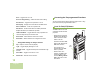
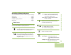
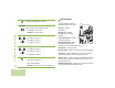
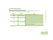
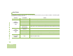
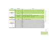
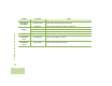
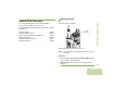
Table Of Contents
- Declaration of Conformity
- Important Safety Information
- Software Version
- Computer Software Copyrights
- Documentation Copyrights
- Disclaimer
- Getting Started
- Preparing Your Radio for Use
- Identifying Radio Controls
- Identifying Status Indicators
- General Radio Operation
- Advanced Features
- Advanced Call Features
- Scan Lists
- Scan
- Call Alert Paging
- Emergency Operation
- Secure Operations
- Trunking System Controls
- Utilities
- Using the Flip Display
- Selecting a Zone Bank
- Selecting the Power Level
- Controlling the Display Backlight
- Turning Voice Mute On or Off
- Using the Time-Out Timer
- Using the Conventional Squelch Operation Features
- Using the PL Defeat Feature
- Using the Digital PTT ID Feature
- Using the Smart PTT Feature (Conventional Only)
- Voice Announcement
- Helpful Tips
- Accessories
- Appendix: Maritime Radio Use in the VHF Frequency Range
- Glossary
- Commercial Warranty
- Notes
Identifying Status Indicators
English
11
Identifying Status Indicators
Your radio indicates its operational status through the following:
Status Icons. . . . . . . . . . . . . . . . . . . . . . . . . . . . . . . . . page 11
LED Indicator. . . . . . . . . . . . . . . . . . . . . . . . . . . . . . . . page 12
Intelligent Lighting Indicators. . . . . . . . . . . . . . . . . . . . page 13
Alert Tones . . . . . . . . . . . . . . . . . . . . . . . . . . . . . . . . . page 14
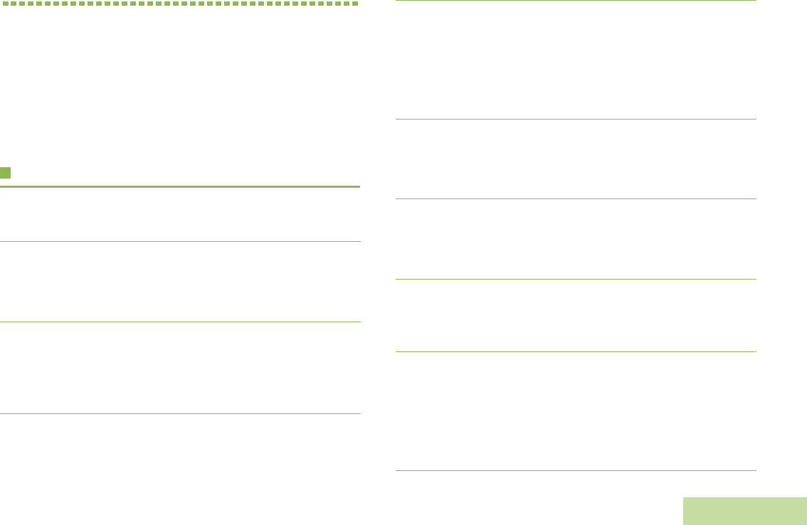
Status Icons
The 112 x 32 pixel top monochrome display screen of your radio
shows the radio status and operating conditions.
Battery
The icon shown indicates the charge remaining in
the battery. Blinks when the battery is low.
Received Signal Strength Indicator (RSSI)
The number of bars displayed represents the
received signal strength for the current site, for
trunking only. The more stripes in the icon, the
stronger the signal.
U
V
Direct
• On = Radio is currently configured for direct
radio to radio communication (during
conventional operation only).
• Off = Radio is connected with other radios
through a repeater.
Monitor (Carrier Squelch)
Selected channel is being monitored (during
conventional operation only).
Power Level
• L = Radio is set at Low power.
• H = Radio is set at High power.
Scan
Radio is scanning a scan list.
Priority Channel Scan
• Blinking dot = Radio detects activity on
channel designated as Priority-
One.
• Steady dot = Radio detects activity on channel
designated as Priority-Two.
N
M
H
or L
J
j