
User's Manual


The DIOS PIU and Piccolo-XR Units
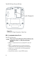
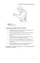
PIU Connectors
The PIU connectors (see Figure 18):
• RS232 (RJ45, 8 pin)
• RS485 (RJ10, 4 pin)
• Adapter port (RJ10, 4 pin)
• PGND And Power Switch (TB 3 pin)
• 24 V AC PWR IN (2 pin)
• 6, 9, 12 V DC Battery Input (2 pin)
PIU LED Operation
Three software programmable LED indicators are located on
the PIU enclosure (see Figure 18). These indicators can be used
for diagnostics purposes.
• Radio TX/RX (RED): ON – a valid frame is received by the
internal DPSK modem or the PIU transmits a frame.
• RS232/RS485 RX/TX (ORANGE): ON – a valid frame is
received or transmitted through the RS232/RS485 port
(UART1).
• Adapter port TX/RX (GREEN): ON – a valid frame is
received or transmitted through the adapter port (UART2),
or the Radio is being programmed.
29