
User's Manual

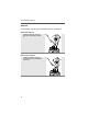
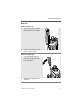

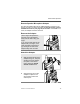

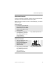

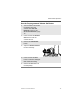

Table Of Contents
- ASTRO XTS 2500 Digital Portable Radio Model I User Guide
- Product Safety and RF Exposure Compliance
- Computer Software Copyrights
- Documentation Copyrights
- Disclaimer
- Contents
- General Radio Operation
- Notations Used in This Manual
- XTS 2500 Model I Radio
- Physical Features of the XTS 2500 Model I Radio
- Programmable Features
- LED Indicators
- Alert Tones
- Standard Accessories
- Universal Connector Cover
- Remote Speaker Microphone Adapter
- Radio On and Off
- Zones and Channels
- Receive / Transmit
- Conventional Mode Operation
- Common Radio Features
- Special Radio Features
- Helpful Tips
- Accessories
- Appendix: Maritime Radio Use in the VHF Frequency Range
- Glossary
- Commercial Warranty
- Index

12
General Radio Operation
Universal Connector Cover
The universal connector cover is located on the antenna side of the
radio. It is used to connect certain accessories to the radio.
Note: To prevent damage to the connector, shield it with the
connector cover when not in use.
Remove the Connector Cover
Attach the Connector Cover
1 Insert a flat-bladed
screwdriver into the area
between the bottom of the
cover and the slot below the
connector.
2 Hold the top of the cover with
your thumb while you pry the
bottom of the cover away
from the radio with the
screwdriver.
1 Insert the hooked end of the
cover into the top of the
connector. Press downward
on the cover’s top to seat it
into the slot.
2 Press the cover’s lower tab
below the connector until it
snaps in place.
Top
Slot
Bottom
Slot
Top
Hooked End
Bottom
H
ooked End
Tab