
Installation Guide
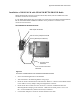
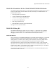
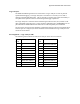
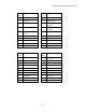
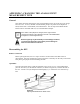
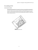
Table Of Contents
- MOSCAD-M Remote Terminal Unit
- CONTENTS
- INTRODUCTION
- INSTALLATION
- THE MOSCAD˚M UNIT
- POWER MANAGEMENT
- ETHERNET INTERFACE OPTION
- APPENDIX A: CABLES AND ADAPTERS
- APPENDIX B: MODELS AND ACCESSORIES
- APPENDIX C: CHANGING THE ANALOG INPUT MEASUREMENT TYPE

Appendix C: Changing the Analog Input Measurement Type
48
Place Jumpers
Flip over the Expansion board. Locate the four jumpers marked P7, P8, P9, and P10, near the
center of the board, as shown in Figure 27. All jumpers which are placed measure 4-20mA.
To change an AI to 0-5V, remove the jumpers. Make sure to save the cap. To change an AI to
4-20mA, place the jumpers. Press the cap down until you hear it click.
Figure 27
Expansion Board with Jumpers
The chart below shows the correlation of jumpers to AIs.
AI1 AI2 AI3 AI4
P7 P8 P9 P10