
Installation Guide
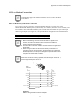
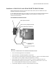
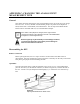
Table Of Contents
- MOSCAD-M Remote Terminal Unit
- CONTENTS
- INTRODUCTION
- INSTALLATION
- THE MOSCAD˚M UNIT
- POWER MANAGEMENT
- ETHERNET INTERFACE OPTION
- APPENDIX A: CABLES AND ADAPTERS
- APPENDIX B: MODELS AND ACCESSORIES
- APPENDIX C: CHANGING THE ANALOG INPUT MEASUREMENT TYPE

46
APPENDIX C: CHANGING THE ANALOG INPUT
MEASUREMENT TYPE
General
This chapter describes changing the units of measurements of the AIs, from current to voltage
and vice versa. To do so, the RTU is disassembled, jumpers are placed on the Expansion
board, and the unit is reassembled, as described below. The AI setup of the MOSCAD-M
PLUS radios is described under AI (x4) in the Installation chapter.
If the status of the jumpers is changed, the AI Type must be
changed accordingly in the Hardware Test tool of the MOSCAD-M
Configurator. See Configurator help.
Before beginning any disassembly or reassembly procedures,
you should be adequately grounded to prevent damage to
static sensitive devices in the unit.
Disassembling the RTU
Remove Connectors
Before opening the RTU, the five 10-pin connectors on the bottom of the RTU must be
disconnected. Note the configuration of the connections so that they can be easily reconnected
after placing the jumpers and reassembling the RTU.
Open RTU
Turn the unit upside down, so that the rightmost wing is closer to you. Using both thumbs,
press the two tabs (A) at the bottom of the unit, as shown in Figure 24, to release the back of
the case. Lift the cover (B) and push forward slightly (C), to release the cover from the top
tabs.
Figure 24
Opening MOSCAD-M RTU Plastic Case