
Installation Guide
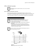
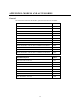
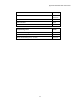
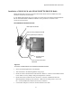
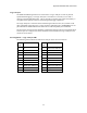
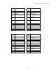
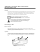
Table Of Contents
- MOSCAD-M Remote Terminal Unit
- CONTENTS
- INTRODUCTION
- INSTALLATION
- THE MOSCAD˚M UNIT
- POWER MANAGEMENT
- ETHERNET INTERFACE OPTION
- APPENDIX A: CABLES AND ADAPTERS
- APPENDIX B: MODELS AND ACCESSORIES
- APPENDIX C: CHANGING THE ANALOG INPUT MEASUREMENT TYPE

Appendix B: Models and Accessories
44
Logic Analyzer
The MOSCAD-M debug board can be connected to a Logic Analyzer in order to perform
sophisticated debugging. The Logic Analyzer is used when it is necessary to see what is
running on the data and address bus. This is generally in extreme cases where the memory is
corrupted and the problem cannot be found using the debugger capabilities.
The Logic Analyzer is connected to the board through connectors P12, P13, and P14 on the
upper right-hand side of the board. These connectors (Motorola part # 2808044H09) are not
provided with the MOSCAD-M board and must be ordered separately and assembled.
The pins of the connection cable should be configured according to the Pin Assignment below.
Once the pins are configured, the cables should be connected from the Logic Analyzer to the
connectors on the board.
Pin Assignment – Logic Analyzer TBs
The following charts indicate the function of each pin in the various connectors.
P12
Pin #
Function P12
Pin #
Function
1 NC 11 Address bus Add bit 8
2 NC 12 Address bus Add bit 7
3 PG0_DTACK 13 Address bus Add bit 6
4 Address bus Add bit 15 14 Address bus Add bit 5
5 Address bus Add bit 14 15 Address bus Add bit 4
6 Address bus Add bit 13 16 Address bus Add bit 3
7 Address bus Add bit 12 17 Address bus Add bit 2
8 Address bus Add bit 11 18 Address bus Add bit 1
9 Address bus Add bit 10 19 PG1_A0
10 Address bus Add bit 9 20 GND