
Installation Guide
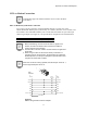
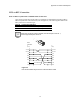
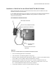
Table Of Contents
- MOSCAD-M Remote Terminal Unit
- CONTENTS
- INTRODUCTION
- INSTALLATION
- THE MOSCAD˚M UNIT
- POWER MANAGEMENT
- ETHERNET INTERFACE OPTION
- APPENDIX A: CABLES AND ADAPTERS
- APPENDIX B: MODELS AND ACCESSORIES
- APPENDIX C: CHANGING THE ANALOG INPUT MEASUREMENT TYPE

Appendix B: Models and Accessories
43
Debug Setup
By default, downloading from the PC to the unit is done via Port 2. When the unit is first
powered up, LED 12 (CM2) should be lit, indicating that the debugger should be downloaded
via Port 2.
In order to connect to Port 1, a modified system file must be downloaded to the flash. This file
is available from the factory.
To set up the system for debugging, do as follows:
a) Compile and link your application using Microtec tools.
b) Connect the MOSCAD-M Configurator to the debug board as you would the standard
MOSCAD-M board.
c) In the Site Configuration utility, set Port 2 to Not Used.
d) Download the site configuration.
e) Connect Port 1 of the RTU to the COM port of the PC.
f) Switch off the RTU, then switch it on again, while the push-button is pressed. The system
will then be in bootstrap mode where a new system can be downloaded.
g) If a communication session is open with the RTU, make sure to use the Stop
Communication utility in the Configurator.
h) In the Downloader utility, make sure the proper PC COM port is specified in the download
session and download the system file using the MMxyyD2.KRL file. The .krl file, which
is found in the C:\MConf150\system directory when the debug system is installed,
downloads the corresponding system and kernel files to the RTU.
i) Make sure that the CM2 LED is lit, indicating that the port is ready to communicate with
the Microtec debugger.
j) Connect Port 2 of the RTU to the PC COM port on which the XRAY debugger runs.
k) Copy the include file (e.g. MM_V100.inc) which suits your MOSCAD-M version into the
directory. Compile and link your source files.
l) Use the MCDEBUG.BAT file to load the ‘C’ application into the RAM.
m) Follow the debug instructions in the ‘C’ Toolkit for MOSCAD Family RTUs manual.
If the unit is powered off or if the main power input falls below 3.1V
DC, the RAM data will not be retained and the debugger will have to
be downloaded again.