
Installation Guide
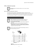
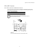
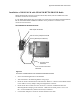
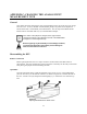
Table Of Contents
- MOSCAD-M Remote Terminal Unit
- CONTENTS
- INTRODUCTION
- INSTALLATION
- THE MOSCAD˚M UNIT
- POWER MANAGEMENT
- ETHERNET INTERFACE OPTION
- APPENDIX A: CABLES AND ADAPTERS
- APPENDIX B: MODELS AND ACCESSORIES
- APPENDIX C: CHANGING THE ANALOG INPUT MEASUREMENT TYPE
Appendix B: Models and Accessories
42
MOSCAD-M Installation Kit for GP140/GP328/HT750/PRO5150 Radios
The MOSCAD-M Installation Kit for GP140/GP328/HT750/PRO5150 Radios enables users to
install a GP140, GP328, HT750 or PRO5150 radio (externally) to the MOSCAD-M. The
Installation Kit includes:
• Mounting Bracket (FCN5516A)
• Audio Communication Cable (FKN5953A)
• Audio Accessory Adapter (HLN9716B)
• DC Power Cable (FKN4465A)
• BNC Adapter (HLN9756A)
• DIN Rail Radio Connectors (Part #0786144U05)
See Figure 23 for connection details.
MOSCAD-M Debug Kit
The MOSCAD-M Debug kit enables the user to debug a ‘C’ application using the XRAY
debugger. Set up the MOSCAD-M Configurator PC as described below, then follow the
debugging instructions in the ‘C’ Toolkit for MOSCAD Family RTUs manual.
MOSCAD-M Board
The kit consists of a special MOSCAD-M board, specifically built for debugging. The system
software (system.krl) is burned into the flash memory at the factory. Another system file
(MmxyyD2.krl) is available with the Debug System Installation (FVN9779) MOSCAD-M
Configurator and must be downloaded before using the Microtec XRAY debugger.
The debug board has no plastic housing and all components are visible. Next to the push-
button there are two additional buttons which do not exist in the standard MOSCAD-M. The
leftmost button is Reset. The rightmost button is NMI (Non Masked Interrupt). The NMI (or
CTRL+C from the PC keyboard) will stop the program.
Two megabytes of RAM are installed in the debug board to enable downloading the system
software from the PC to the unit.