
Installation Guide
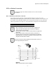
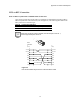
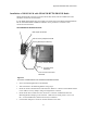
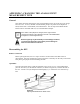
Table Of Contents
- MOSCAD-M Remote Terminal Unit
- CONTENTS
- INTRODUCTION
- INSTALLATION
- THE MOSCAD˚M UNIT
- POWER MANAGEMENT
- ETHERNET INTERFACE OPTION
- APPENDIX A: CABLES AND ADAPTERS
- APPENDIX B: MODELS AND ACCESSORIES
- APPENDIX C: CHANGING THE ANALOG INPUT MEASUREMENT TYPE

Appendix B: Models and Accessories
41
Installation of MOSCAD-M with GP140/328/HT750/PRO5150 Radio
MOSCAD-M models which are equipped with GP140, GP328, HT750 or PRO5150 radios
should be connected as shown below.
If your MOSCAD-M model does not include one of these radios, the MOSCAD-M Installation
Kit for GP140/GP328/HT750/PRO5150 Radios can be purchased. The radio is then
connected as shown below.
Figure 23
Connection of MOSCAD-M to GP140/328/HT750/PRO5150 Radio
• Secure the Mounting Bracket to the DIN Rail.
• Attach the radio to the Mounting Bracket using snaps.
• Route the Audio Communication Cable from the “PORT 3” connector of the MOSCAD-M
to the Audio Accessory Adapter. Plug in and tighten the connector.
• Route the DC Power Cable from the “AUX. DC” connector of MOSCAD-M to the
Mounting Bracket and plug in the connector. Make sure the AUX power is set to 7.5V
DC. Set the middle knob (channel select knob) to Channel 1.
• Use the BNC Adapter to connect an external antenna to the radio.
Mounting Bracket (Kit FCN5516A)
Audio Communication Cable
FKN8023A
DC Power Cable
FKN4465A
Audio Accessory Adapter HLN9716B
GP140/GP328/HT750/PRO5150 Radio
BNC Adapter HLN9756A