
Installation Guide
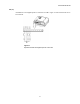
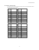
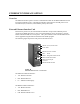
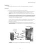
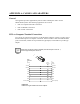
Table Of Contents
- MOSCAD-M Remote Terminal Unit
- CONTENTS
- INTRODUCTION
- INSTALLATION
- THE MOSCAD˚M UNIT
- POWER MANAGEMENT
- ETHERNET INTERFACE OPTION
- APPENDIX A: CABLES AND ADAPTERS
- APPENDIX B: MODELS AND ACCESSORIES
- APPENDIX C: CHANGING THE ANALOG INPUT MEASUREMENT TYPE

The MOSCAD-M Unit
29
Pin Assignment - Expansion Board TBs
The following charts indicate the function of each pin in the various terminal blocks (TBs) on
the Expansion board as shown in Figure 9.
TB5
(DI/AO)
Pin #
Function TB6
(AI)
Pin #
Function
1 DI13 1 PGND
2 COM DI13-DI14 2 AI1 +
3 DI14 3 AI1 -
4 DI15 4 AI2 +
5PGND 5AI2 -
6 Vin + 6 AI3 +
7 Vin - 7 AI3 -
8 Iout 8 AI4 +
9 COM AO 9 AI4 -
10 Vout 10 PGND
Backup Battery
Below 8.9V DC, the unit enters Low Power Sleep mode. As long as the input power is above
6V DC, the unit is still powered from the main power supply input. If the input power drops
below 6V DC, the unit will use the backup battery to preserve the contents of the RAM and
Real Time Clock (RTC) data. In this case, the unit is in Low Power Sleep mode and not in
Reset mode. This means that the status of outputs 1 to 8 is preserved.
The battery will retain the data for at least 70 days (cumulative). Power consumption from the
backup battery will be <5mA @ 4.5V DC.
If no backup battery is detected, or if the backup battery falls below 3.1V DC (power fail), the
unit will shut down until power is restored. In this case, the RAM and Real Time Clock
(RTC) data will not be retained. LED 4 (BATT) will indicate when the backup battery voltage
drops below 3.5V. This indication is also available for the user application. Under these
circumstances, the SS1 and SS2 Solid State switches are turned off even if they were set to
independent operation mode.