
Installation Guide
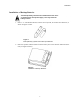
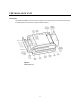
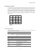
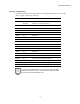
Table Of Contents
- MOSCAD-M Remote Terminal Unit
- CONTENTS
- INTRODUCTION
- INSTALLATION
- THE MOSCAD˚M UNIT
- POWER MANAGEMENT
- ETHERNET INTERFACE OPTION
- APPENDIX A: CABLES AND ADAPTERS
- APPENDIX B: MODELS AND ACCESSORIES
- APPENDIX C: CHANGING THE ANALOG INPUT MEASUREMENT TYPE

The MOSCAD-M Unit
16
IO1 Page LED Functions
The following table describes the functions of the diagnostic LEDs when set to the IO1
(Page 1) toggle or display (IO1 LED on).
Name On/Off Function/Indication
CPU Off
Flashing: FPGA is not loaded correctly.
IO1 On Display is in IO1 page.
IO2 Off
IO3 Off
LED 1 On DI1 is on.
LED 2 On DI2 is on.
LED 3 On DI3 is on.
LED 4 On DI4 is on.
LED 5 On DI5 is on.
LED 6 On DI6 is on.
LED 7 On DI7 is on.
LED 8 On DI8 is on.
LED 9 On DI9 is on.
LED 10 On DI10 is on.
LED 11 On DI11 is on. (Can be fast counter)
LED 12 On DI12 is on. (Can be fast counter)
LED 13 On DI13 is on. (Models with expansion board only)
LED 14 On DI14 is on. (Models with expansion board only)
LED 15 On DI15 is on. (Models with expansion board only)
The LED is not updated after each change in DI status, but rather
after the user performs a scan. Thus, the status of the DI reflects
the status as of the last software scan.