
Installation Guide
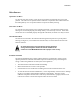
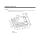
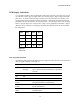
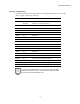
Table Of Contents
- MOSCAD-M Remote Terminal Unit
- CONTENTS
- INTRODUCTION
- INSTALLATION
- THE MOSCAD˚M UNIT
- POWER MANAGEMENT
- ETHERNET INTERFACE OPTION
- APPENDIX A: CABLES AND ADAPTERS
- APPENDIX B: MODELS AND ACCESSORIES
- APPENDIX C: CHANGING THE ANALOG INPUT MEASUREMENT TYPE

The MOSCAD-M Unit
14
LED Display Indications
A 5 × 4 matrix of LEDs is used for diagnostics and testing of the unit (see Figure 10). The top
row indicates to which page or toggle (CPU, IO1, IO2, IO3, Page 4, Page 5, Page 6) the LED
panel is set. To advance from one page to another, press the push-button once quickly. The
first depression of the push-button activates the display. Subsequent short depressions of the
push-button advance the display to the next page: CPU > IO1 (I/O Page 1-DI) > IO2 (I/O Page
2-DO) > IO3 (I/O Page 3-AI) > Page 4 (AO) > Page 5 (User Application Controlled) > Page 6
(Hardware Test Controlled). In each page, the LEDs have different functions, as described in
the charts below.
CPU IO1 IO2 IO3
15913
2 6 10 14
3 7 11 15
4 8 12 16
Figure 10
LED Panel
CPU Page LED Functions
The following table describes the functions of the diagnostic LEDs when set to the initial CPU
(Page 0) toggle or display (CPU LED on).
Name On/Off Function/Indication
CPU On:
Flashing:
Display is in CPU mode.
CPU is in bootstrap mode OR FPGA is not loaded
correctly.
IO1 Off
IO2 Off
IO3 Off
LED 1
LOAD
On A file (e.g. configuration, application program) is
being downloaded to FLASH memory.
LED 5
CONF
On A Site configuration definition has been loaded
into FLASH memory.
LED 9
APPL
On An application program has been loaded into
FLASH memory.