
Installation Guide
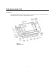
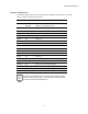
Table Of Contents
- MOSCAD-M Remote Terminal Unit
- CONTENTS
- INTRODUCTION
- INSTALLATION
- THE MOSCAD˚M UNIT
- POWER MANAGEMENT
- ETHERNET INTERFACE OPTION
- APPENDIX A: CABLES AND ADAPTERS
- APPENDIX B: MODELS AND ACCESSORIES
- APPENDIX C: CHANGING THE ANALOG INPUT MEASUREMENT TYPE

The MOSCAD-M Unit
12
Communication Ports
The MOSCAD-M RTU has 3 ports available:
PORT 1 - RS232 Configurator Port (for programming and monitoring the unit), RS232
External Dialup Modem, or RS485 Communication, User protocol
(1A is used for RS485)
(1B is used for RS232)
PORT 2 – Secondary Port RS232 (User protocol)
PORT 3 – External Radio interface
Ports 2 and 3 can work simultaneously with each other and with either Port 1A or Port 1B.
Ports 1A and 1B cannot work simultaneously. Port 3 cannot be used when an internal radio is
installed.
Connectors
The MOSCAD-M RTU has the following connectors available (see Figure 9):
RS485 Port 1A (RJ45, 4 pin)
RS232 Port 1B (RJ45, 8 pin)
RS232 Port 2 (RJ45, 8 pin)
External Radio Port 3 (RJ45, 8 pin)
AUX out for external radio power supply (2 pin)
Power In/Solid State DO (10 pin) - TB1
DO (10 pin) – TB2
DO/DI (10 pin) – TB3
DI (10 pin) – TB4
DI/AO (10 pin) – TB5
AI (10 pin) - TB6
The MOSCAD-M RTU has the following internal connectors.
Internal radio connector (14 pin)
Backup Battery connector (2 pin)
I/O Expansion connector (26 pin)
Controls and Indicators
The push-button is used to activate the LED panel, to toggle the LED panel so that it displays
the status of the CPU or of the I/Os, to initiate software downloading to the CPU, and to erase
User Flash memory and RAM.