
Installation Instructions
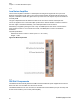
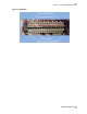


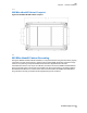
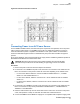
Table Of Contents

Figure 26: Antenna Connection Locations
4.4
Connecting Power to an AC Power Source
For the 900MHz eNodeB Cabinet, the main frame power requires 20 A receptacles, due to the power
rating of the AC power supply. Four 6’ NEMA 5-15p to IEC C15 cables are provided to connect to
server and transceiver power. A separate circuit breaker for each power cable is recommended to
ensure that redundant equipment does not simultaneously lose power when a breaker is tripped or
opened.
All AC power breakers, wiring and receptacles must comply with the installation guidelines specified in
Standards and Guidelines for Communication Sites.
CAUTION: Ensure that the AC power source and/or breaker(s) are OFF and all safety
precautions and procedures for the safe handling of high energy sources are followed.
Procedure:
1 Remove the power cords from the loose shipment accessories.
2 For each IEC C19 to NEMA 5-20 power cords, insert the C19 connectors of the cables into the
IEC C-20 connectors on the junction. Select the connectors depending on the cabinet sector:
•
For one sector cabinets select the connectors labeled “POWER SUPPLY 1”, “POWER
SUPPLY 2” and “POWER SUPPLY 3”.
• For two sector cabinets, make the connections for 1 sector cabinets as well as “POWER
SUPPLY 4”.
• For three sector cabinets, make the connections for 2 sector cabinets as well as “POWER
SUPPLY 5”.
3 For each IEC C15 to NEMA 5-15 power cords, insert the C15 connectors of the cables into the
IEC C14 connectors on the junction panel labeled “TRANSCEIVER 1”, “TRANSCEIVER 2”,
“SERVER 1” and “SERVER 2”.
4 Place the cable retention clip over the strain relief of the C19 and C15 connectors of the power
cords, and squeeze it to clamp on and retain the cable from accidental removal.
5 Connect the NEMA 5-20 and NEMA 5-15 plugs into a compatible wall receptacle to apply power.
TBD
Chapter 4 : Hardware Installation
37
Exhibit D page 38 of 38