
Installation Instructions
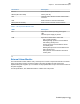

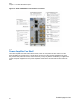
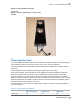
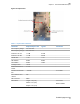
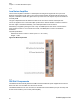
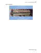
Table Of Contents

Figure 17: Power Amplifier Fan Shelf
Parameters:
521mm x 137mm x 81mm (20.51" x 5.39" x 3.19")
4.25 lbs
2.11
Power Amplifier Shelf
The Power amplifier shelf houses up to 6 power amplifiers. This shelf is strictly for mechanical support
of the amplifiers and does not electrically connect in any way to the power amplifiers.
The power amplifiers are mounted within the shelf and two power amplifiers are required to support
each sector.
48V DC supplies the power amplifier after passing through a 30A circuit breaker.
Once power is applied, an internal FPGA is used to initialize and enable the amplifier as well as to
manage the various health monitoring of both the amplifier and the fan kit to which it is attached.
The power amplifier accepts the low level signal from the TEKO shelf and amplifies it nominally by
40dB to a maximum power of 100W at the Tx OUT port. Maximum current is There is no gain or power
adjustment available in the amplifier. The drive from the low level transceivers are adjusted in order to
achieve the desired power at the top of the rack.
The alarm interface is connected to the external alarm module in the TEKO sub-rack and supplies a
dry contact interface.
Table 10: Power Amplifier Specifications
NB1 (standalone) 1.4 MHz LTE 3 MHz LTE
Power (W) 60 100 100
TBD
Chapter
2 : 900 MHz eNodeB Description
25
Exhibit D page 26 of 38