
Installation Instructions
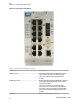
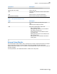

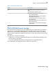
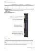
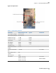
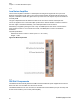
Table Of Contents

Connectors Description
EXT IN External alarms input connector.
RS232 (TSPV-R models) Factory use only.
ANT Optional built-in wireless modem antenna SMA
connector.
LAN RJ45 connector Local Control Interface.
WAN (TSPV-Ex models) RJ45 connector Remote Control Interface.
Table 7: LTE Supervision Module LEDs
LEDs Description
ON Supervision Module operating status green
LED:
ON when power supply is present.
ALM Supervision Module alarm status LED.
OFF: regular operation
Blinking Orange: presence of active alarms
with warning severity level
Orange: presence of active alarms with mi-
nor severity level
Blinking Red: presence of active alarms with
major severity level
Red: presence of active alarms with critical
severity level
2.8
External Alarm Module
The external alarm module utilizes 16 dry contact inputs to monitor components external to the TEKO
shelf. The module is used to monitor the health of the power amplifiers as well as the power
amplifier/LNA power supplies. Up to 4 modules can be populated with one per sector and the fourth for
the power supplies.
For full specifications, see TEKO DAS Platform - Master Unit Components.
TBD
Chapter 2 :
900 MHz eNodeB Description
21
Exhibit D page 22 of 38