
Installation Instructions

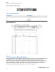
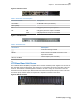
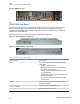
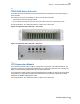
Table Of Contents

Figure 6: DAS Front View
Table 3: DAS Front View Description
Connectors/LEDs Description
AC MAINS~ AC MAINS socket (100-240Vac)
Label (LEDs):
AC ON (green) when AC input is present
DC OK ON (green) when DC output is available
FAIL ON (red) when DC output is unavailable
Figure 7: DAS Rear View
Table 4: DAS Rear View
Connectors Description
Protective earthing terminal
RS485 RJ45 connector for RS485 connection to the
Supervision Module
28V ; 10A MAX
28Vdc Outputs (max 10A each)
2.4
LTE Base Band Unit Server
The LTE Base Band Unit (BBU) is supplied via AC and has redundant power supplies so it has two AC
line cords that need to be plugged in. The Core’s S1 is connected to the server in the back of the unit
via eno2. The interface to the management software is via en01. Lastly, the connection to the LTE
Transceiver rack is via fiber optic cable between the CIPRI card output and the input to the LTE Point
of Interface (POI) modules. Each POI represents a separate connection to the server.
Figure 8: BBU Front View
TBD
Chapter
2 : 900 MHz eNodeB Description
17
Exhibit D page 18 of 38