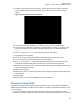
6802800U74-AP Chapter 7: Radio Frequency Distribution System 3 Loosen the all the locking knobs of the MTCC, see the figure below (the design of the MTCC may look slightly different), and turn the tuning knobs counter clock wise as many turns as possible. Figure 159: Tuning Knob and Locking Knob Tuning knob BR 1 BR 2 Locking knob 4 Power up the BTS and let all BRs key up. Observe that the TX LEDs of all BRs shine. 5 Connect the service computer to the service port of Base Radio 1 and log on.
6802800U74-AP Chapter 7: Radio Frequency Distribution System to the Exp Cabinet connector on the Duplexer/Preselector present in the MTS 4 Prime Cabinet giving the right signal level for the RX-Splitter. • Cavity Combiners – combining of eight carriers on 1 TX antenna. Table 84: MTS 4 Expansion Cabinet RF Configurations on page 310 lists the RF configurations of the MTS 4 Expansion Cabinet.
6802800U74-AP Chapter 7: Radio Frequency Distribution System RF Configuration TX on 1 ant., RX on 3 ant. Max Power (W) Low Pwr High Pwr 8 20 Cavity Combiner 2 (comb) + phasing harness RX Splitter 3 NOTICE: For 260 MHz version of MTS there are no phasing harness configurations, so please disregard from these in Table 84: MTS 4 Expansion Cabinet RF Configurations on page 310. Figure 160: Expansion Cabinet with Single Diversity MTS 4 PRIME CABINET FILTER REAR VIEW BR1 BR2 BR3 BR4 Exp.
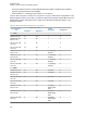
6802800U74-AP Chapter 7: Radio Frequency Distribution System Figure 161: Expansion Cabinet with Dual Diversity MTS 4 PRIME CABINET FILTER REAR VIEW BR1 BR2 BR3 BR4 FILTER REAR VIEW Exp. Cabinet BR1 RX SPLITTER REAR VIEW MTS 4 EXPANSION CABINET 312 BR1 BR2 BR3 BR4 Prime Cab BR2 BR3 BR4 Exp.
6802800U74-AP Chapter 7: Radio Frequency Distribution System Figure 162: Expansion Cabinet with Triple Diversity MTS 4 PRIME CABINET FILTER REAR VIEW BR1 BR2 BR3 BR4 Exp. Cabinet FILTER REAR VIEW BR1 BR2 BR3 BR4 Exp. Cabinet RX SPLITTER REAR VIEW MTS 4 EXPANSION CABINET BR1 BR2 BR3 BR4 Prime Cab FILTER REAR VIEW BR1 BR2 BR3 BR4 Exp. Cabinet RX SPLITTER REAR VIEW BR1 BR2 BR3 BR4 Prime Cab RX SPLITTER REAR VIEW BR1 BR2 BR3 BR4 Prime Cab 7.4.
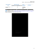
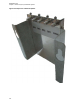
802800U74-AP Chapter 7: Radio Frequency Distribution System Figure 163: Expansion Cabinet RX Splitter 314
6802800U74-AP Chapter 7: Radio Frequency Distribution System Figure 164: Schematic Diagram of RX Splitter Splitter DC brick RX BR5 DC brick RX BR6 DC brick RX BR7 DC brick RX BR8 RX Prime Cabinet 7.4.1.1 Replacing the Expansion Cabinet RX Splitter This process outlines the recommended tasks to be performed to replace the Expansion Cabinet RX Splitter. For a list of available FRUs, see Field Replaceable Units (FRUs) on page 478.
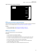
6802800U74-AP Chapter 7: Radio Frequency Distribution System 7.4.1.1.2 Reinstalling the RX Splitter This procedure describes how to reinstall the RX Splitter. Procedure: 1 Fasten the RX Splitter onto the bracket. 2 Slide the RX Splitter into the cabinet. 3 Tighten the two fastening screws at the front. 4 Connect the RX cables to the back of the RX Splitter. 5 Slide on the top rear and front panels and fasten these with screws. 6 Place the front panel back on and screw this into place.
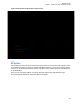
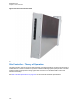
6802800U74-AP Site Controller Chapter 8 Site Controller The following figures show the front and the rear view of the site controller.
6802800U74-AP Chapter 8: Site Controller Figure 166: Site Controller Rear View 8.1 Site Controller – Theory of Operation The Site Controller controls resources within the MTS, including assignment of frequencies and slots to mobile stations. The Site Controller incorporates a Global Positioning System (GPS) module. The GPS module provides a high precision timing signal used as reference for the Base Radio receive and transmit functionality.
6802800U74-AP Chapter 8: Site Controller Figure 167: Site Controller - Functional Block Diagram RAM MEMORY FLASH MEMORY RS232 SERIAL (RJ45) X.
6802800U74-AP Chapter 8: Site Controller 8.2 Site Controller – Indicators, Switches, and Connectors This section contains information on indicators, switches, and connectors of the Site Controller.
6802800U74-AP Chapter 8: Site Controller 8.2.1 Site Controller – Front Panel BTSQ108SSR_MTS2and4_dr_SCCaptiveScrews_A Figure 168: Site Controller - Front Panel SITE CONTROLLER Power 2 Power 1 BR1 BR3 BR2 BR4 CAN E1 Service Red In Exp. Cab Red.
6802800U74-AP Chapter 8: Site Controller 8.2.1.1 Site Controller – Front Panel Indicators (LED) Figure 169: Site Controller - Front Panel LEDs Position LED10 LED9 BR1 BR3 BR2 BR4 CAN E1 LED6 LED5 LED12 LED11 LED8 LED7 LED16 LED15 Not used LED18 LED17 Service Exp. Cab.
6802800U74-AP Chapter 8: Site Controller LED LED/Port Name Position Controlled by Indication • GREEN/AMBER Blinking: BTS synchronized to a standby SC. • AMBER Blinking: In training. • AMBER: GPS Free run mode synchronized (ETSI spec). • RED: NTP, NTP malfunction. • RED Blinking: Calibration is required. • GREEN/RED Blinking: Frequency lock is required, pull in.
6802800U74-AP Chapter 8: Site Controller LED LED/Port Name LED5 LED6 BR1 LED7 LED8 BR2 LED9 LED1 0 BR3 LED1 1 LED1 2 BR4 LED1 3 LED1 4 Service CAN LED1 5 324 E1 Position Controlled by Indication Port 1 LED1 HW, Enet switch • OFF: Ethernet link not present. • GREEN: Ethernet link present. Port 1 LED2 HW, Enet switch • OFF: Ethernet activity not present. • YELLOW: Ethernet activity present. Port 2 LED1 HW, Enet switch • OFF: Ethernet link not present.
6802800U74-AP Chapter 8: Site Controller LED LED/Port Name LED1 6 Controlled by Port 7 LED2 LED1 7 LED1 8 Position Port 8 LED1 Exp.Cab. Port 8 LED2 Indication • GREEN: Primary E1 OK (no LOS (Loss Of Signal)). • AMBER: Errors FE, CRC, BPV, PD. • RED: Primary E1 failure LOS. • OFF: Secondary E1 not configured. • GREEN: Secondary E1 OK (no LOS (Loss Of Signal)). • AMBER: Errors FE, CRC, BPV, PD. • RED: Secondary E1 failure LOS. • OFF: Ethernet link not present.
6802800U74-AP Chapter 8: Site Controller Connector Name Connector Type To/From Comment E1 RJ45 Junction Panel Pin connections on the Site Controller are different from the ones on the Junction Panel connector. Service RJ45 Service Terminal Provides service access. See Table 88: Site Controller - Service Cable Pinouts on page 326 for service cable pinout information. (Service Cable PN: 3066565B) Exp.Cab.
6802800U74-AP Chapter 8: Site Controller 8.2.2 Site Controller Rear Panel Figure 170: Site Controller Rear Panel 1 2 1 — X21/Remote GPS 2 — Alarms/Control 8.2.2.1 Site Controller – Rear Panel Connectors Table 89: Site Controller - Rear Panel Connectors Connector Name Connector Type To/From Comment Remote GPS/ X.21 IDE 26pin Junction Panel Connects to remote GPS/ X.21 Alarms/Control IDE 34pin Junction Panel Provides Alarm/Control interface 8.
6802800U74-AP Chapter 8: Site Controller At initialization of the MTS, the factory configures the Site Controller with a relation between track number and the function of the node. You can modify this configuration in a service situation. If a node is removed or is defective, the Site Controller knows the track number of a non-responding FRU and therefore it can make a proper service report which tells exactly what FRU to replace.
6802800U74-AP Chapter 8: Site Controller Unit Function • Software Fail: Indicating software is corrupted or unable to initialize. • Over Temperature: Indicating over temperature detected 5 °C to 10 °C before shutdown. • Fan 1 alarm: Fan 1 not operating (fan has stopped or its running speed is below specification), PSU has received a high signal (open collector) from fan tray 1 through fan connector 1.
6802800U74-AP Chapter 8: Site Controller Unit Function NOTICE: See the MMI Commands manual for additional information on commands and parameters. ATCC Monitoring: • Cavity status. • ATCC Heartbeat signal: heart beat signal is repeated every 30 s. Alarms: • Software corrupted. • Distance between two channels below 150 kHz. • Cavity VSWR alarm. • Master Slave communication error. • Motor alarm. • Cavity tuning error alarms together. • VSWR exceeded the specified value.
6802800U74-AP Chapter 8: Site Controller Unit Function • VSWR alarm. Controls: • VSWR Alarm Threshold: establishes a threshold for enabling a VSWR Alarm. Valid threshold values are in the range 1.00 to 10.00 where 1.00 means No VSWR. Recommended values for each MTS configuration are: - 400 MHz: 3.00 - 260 MHz: 3.00 - 800 MHz: 4.00 8.3.1 Updating CAN Bus TrackID Mapping List When and where to use: Perform this procedure to update the Mapping List with the New Unit TrackID.
6802800U74-AP Chapter 8: Site Controller 8.4 Site Controller – GPS Module The GPS module generates a highly accurate timing reference signal within the Base Station. The integrated GPS module tracks both GPS and Glonass satellites. At least 1 GPS satellite needs to be traced to provide time reference for the SC. Remote GPS module currently supports GPS and Beidou GNSS. GLONASS on the remote GPS module will be supported in the future.
6802800U74-AP Chapter 8: Site Controller • If the battery is OK there should be no RTC related alarms reported. There is no need to change the Site Controller Lithium Battery. • If the battery still reports RTC related alarms, the battery is not working properly or not working at all. Proceed to Replacing the Site Controller Lithium Battery on page 333. 8.5.3 Replacing the Site Controller Lithium Battery CAUTION: Danger of explosion if battery is replaced incorrectly.
6802800U74-AP Chapter 8: Site Controller Figure 172: Site Controller - Captive Screws SITE CONTROLLER REAR VIEW FRONT VIEW Power Power BR1 BR3 BR2 BR4 CAN E1 Exp. Cab. Red. In Red. Out Active Mode GPS BTS Alarm Reset 334 GPS Alarms/Control Service X.
6802800U74-AP Chapter 8: Site Controller 6 Use the handle, and gently slide the Site Controller from the slot, removing it from the chassis. IMPORTANT: There are cables connected at the rear of the Site Controller. Slide out the Site Controller carefully, tag and disconnect ribbon cables at the rear. 7 Remove the Site Controller cover.
6802800U74-AP Chapter 9: XHUB Controller Chapter 9 XHUB Controller NOTICE: The content of this chapter is only supported in DIMETRA IP system releases D6.0 and later.
6802800U74-AP Chapter 9: XHUB Controller Figure 174: XHUB Controller 337
6802800U74-AP Chapter 9: XHUB Controller 9.1 XHUB Controller – Theory of Operation NOTICE: MTS 4 sites equipped with Site Controller Rev A or B may experience service interruption to Base Radio(s) located in the Expansion Cabinet. Prior to Expansion Cabinet installation, Site Controllers of Rev A or B must be sent to factory for FPGA upgrade or replacement. Please see Motorola Solutions Technical Notifications (MTNs) for more information.
6802800U74-AP Chapter 9: XHUB Controller Figure 175: XHUB Controller – Functional Block Diagram LED’s LEDs Switch Reset / Interrupt To FPGA XHUB FPGA Silvertine Reset / Interupt 6 x CP2 sync CP3 Circuit I/F GPIO EEPROM XO 10MHz Temp. SPI Bus Serial I/O expander Door Alarm JTAG Support 26V6 7V Power Sub system 2.5 V, 3.
6802800U74-AP Chapter 9: XHUB Controller 9.2.
6802800U74-AP Chapter 9: XHUB Controller 9.2.1.1 XHUB Controller – Front Panel Indicators (LED) The following table lists the Front Panel LEDs.
6802800U74-AP Chapter 9: XHUB Controller LED LED/Port Name Controlled By Position Indication LED14 Port 5 LED2 HW, Enet switch OFF: Ethernet activity not present YELLOW: Ethernet activity present LED15 Port 6 LED1 HW, Enet switch OFF: Ethernet link not present GREEN: Ethernet link present Port 6 LED2 HW, Enet switch OFF: Ethernet link not present YELLOW: Ethernet link present Port 7 LED1 HW, Enet switch OFF: Ethernet link not present GREEN: Ethernet link present Port 7 LED2 HW, Enet swi
6802800U74-AP Chapter 9: XHUB Controller Connector Name Connector Type To/From Prime Cab RJ45 SC (in Prime Cab) Comment 9.2.2 XHUB Controller – Rear Panel This section provides information about Rear Panel connectors of the XHUB Controller. 9.2.2.1 XHUB Controller – Rear Panel Connectors The following table lists the rear panel connectors of the XHUB controller.
6802800U74-AP Chapter 9: XHUB Controller 9.3.1 XHUB Controller – FRU Table 95: XHUB Controller - FRU Kit Number GMLN4689A Description XHUB MTS-EXP Controller See Planned Maintenance Inspection (PMI) on page 491 for list of Periodic Maintenance Inspections.
6802800U74-AP Base Radio Chapter 10 Base Radio This chapter covers the following topics: • Base Radio – Overview on page 345 • Base Radio – Theory of Operation on page 346 • Base Radio – Indicators and Connectors on page 352 • Replacing the Base Radio on page 354 10.1 Base Radio – Overview Figure 177: Base Radio The Base Radio provides reliable digital radio capabilities in a compact software-controlled design.
6802800U74-AP Chapter 10: Base Radio For more information on Base Radio indicators and connectors, see Base Radio – Indicators and Connectors on page 352 in this chapter. 10.2 Base Radio – Theory of Operation The Base Radio (BR) provides reliable digital communications capabilities.
6802800U74-AP Chapter 10: Base Radio Figure 178: Base Radio Front Panel 347
6802800U74-AP Chapter 10: Base Radio On the front panel, there is a DC power input, three parallel receiver (RX) inputs, a high power transmitter output signal from the power amplifier, a service port, two interfaces to the Site Controllers, and LED indicators. For more information on the LED indicators, see Table 98: Base Radio – LED Indicators on page 352. The following figures show overall block diagrams of the Base Radios for both architectures: BRArch-1 and BR-Arch-2.
6802800U74-AP Chapter 10: Base Radio Figure 180: BR-Arch-2 Base Radio – Functional Block Diagram RJ45 Flash CP2 Circuit RAM RJ45 BUS Ethernet RJ45 RS232+ trig In/Out Host P1021NXE2DFB RF1 Trig In/Out RX I&Q RF2 DCinj. RX Back end Abacus III RX front end Interface RX I&Q RX I&Q RF3 SPI RX Metering and control CONGO PLL 16.8MHz DSP TMS320C6455 FPGA 16.8MHz Osc.
6802800U74-AP Chapter 10: Base Radio The transmit section of the Base Radio is comprised of the Exciter (EXC) and Power Amplifier (PA). The EXC processes the information to transmit from the BRC in the proper modulation format. This low-level signal is sent to the Power Amplifier where it is amplified to the desired output power level. The PA is a continuous-keyed linear amplifier.
6802800U74-AP Chapter 10: Base Radio Power Amplifiers in BR-Arch-1 Base Radios Power Amplifiers in BR-Arch-1 are available in both high and low power versions. High-power PAs in 400 MHz band are available on two different frequency bands. The following table contains a list of all available PAs in BR-Arch-1 Base Radios.
6802800U74-AP Chapter 10: Base Radio Power Amplifier in BR-Arch-2 Base Radios Power Amplifiers in BR-Arch-2 are available in a single, high-power version capable of running efficiently in low-power setting. This version comes in different frequency bands. The following table contains a list of all available PAs in BR-Arch-2 Base Radios.
6802800U74-AP Chapter 10: Base Radio # LED 4 LED5 LED6 LED7 LED8 LED/Port name BR Alarm Type Red/ Green SC 1 Green SC 1 Yellow SC 2 Green SC 2 Yellow Controlled by SW HW, Enet IC HW, Enet IC HW, Enet IC HW, Enet IC Indication • AMBER: Waiting for SWDL this is where the BR will wait if no Site Controller is present • RED: SW not started, power on • OFF: No alarms • AMBER: BR minor alarm: PA, Exciter, RX, BRC Reduced performance • RED: BR failed: PA, Exciter, RX, BRC • OFF:
6802800U74-AP Chapter 10: Base Radio Name of Connector Type To/From Comment RX3 QMA Preselector/ Duplexer RF RX signal and +7 V dc Tx QMA Hybrid Combiner/ Cavity Combiner RF TX signal Power MOLEX Power Supply Unit Pin 1 - 3 GND Pin 4 +7 V Pin 6 - 7 +28.5 V Pin 5, 8 14 not used Table 100: Base Radio – Service Cable Pinouts RJ45 PIN D-SUB 9 FEMALE PIN Description 1 2 3 4 3 Rx 5 5 GND 7 2 Tx 8 5 GND 6 9 10.
6802800U74-AP Chapter 10: Base Radio 10.4.1 Electrostatic Discharge Precaution The Base Radio circuitry contains many CMOS and other electrostatic discharge sensitive devices. Take precautionary measures to prevent damage of Base Radio modules by static discharge when servicing the equipment. Observe the following additional precautions: • Wear a wrist strap (Motorola Part No. 4280385A59 or equivalent) at all times when servicing the Base Radio to minimize static build up.
6802800U74-AP Chapter 10: Base Radio 10.4.2.2 Reinstalling the Base Radio Procedure: 1 Insert the replacement Base Radio by aligning the side rails with the appropriate rail guides inside the Base Radio chassis. 2 Gently push the replacement module completely into the Base Radio chassis assembly using the module handle(s). 3 Secure the replacement module using two TORX screws removed during module removal. Tighten the screws to a torque of 2.7 Nm. 4 Reconnect the cables to the BR front plate.
6802800U74-AP Power Supply Unit Chapter 11 Power Supply Unit The following figure shows the front of the Power Supply Unit (PSU). Figure 184: Power Supply Unit Front Panel 11.1 Power Supply Unit (PSU) – Theory of Operation Dependent on its configuration the MTS is equipped with one or two high efficiency switch mode Power Supply Units (PSU). The PSU has a nominal AC input of 100VAC/240VAC (45-66 Hz) as well as a DC input of 48VDC.
6802800U74-AP Chapter 11: Power Supply Unit There is an ON/OFF switch on the front panel of the PSU module which connects/disconnects DC output voltages. The PSU operates in the following modes: • DC only operation at -48VDC (within -41VDC to -60VDC). NOTICE: DC operation mode does not allow any battery controlling. • AC only operation at 100/240VAC (within 90 VAC to 264 VAC;) without battery charging.
6802800U74-AP Chapter 11: Power Supply Unit • Over Temperature: Indicating over temperature detected 5 °C to 10 °C before shutdown. • Fan 1 alarm: Fan 1 not operating (fan has stopped or its running speed is below specification), PSU has received a high signal (open collector) from fan tray 1 through fan connector 1. • Fan 2 alarm: Fan 2 not operating (fan has stopped or its running speed is below specification), PSU has received a high signal (open collector) from fan tray 2 through fan connector 2.
6802800U74-AP Chapter 11: Power Supply Unit 11.1.2.1 Backup Battery Charging Procedure NOTICE: Selected Operation Mode: AC Operation The backup battery charging output voltage is 40.5VDC to 57VDC and output current 0 to 6A. A temperature sensor monitors the backup battery temperature to ensure optimum charging.
6802800U74-AP Chapter 11: Power Supply Unit Figure 185: PSU Front Panel POWER SUPPLY UNIT FRONT VIEW POWER SUPPLY Power AC In AC In Status DC In Status DC Out / Temp Pin 1 DC Out. Pin 8 Fan 1 Status Fan 2 Pin 7 Pin 814 Status Fan 3 ATCC DC Out Status Battery Temp. Sens. DC in Battery CAN 1 CAN 2 11.2.1 PSU LED Indicators The following table lists and describes the PSU LED indicators and Figure 185: PSU Front Panel on page 361 shows their position.
6802800U74-AP Chapter 11: Power Supply Unit LED Name DC In Status (DC input and charging indicator) DC Out / Temp.
6802800U74-AP Chapter 11: Power Supply Unit LED Name Color Condition Indications Upper 3 LEDs (AC In Status, DC In Status and DC Out/ Temp.) 3 dual color LEDs: green/red only boot loader is running (meaning that the boot loader waits for an .exe file) 3 LEDs blinking together: R (red) R R -> G (green) G G, with 1 Hz frequency boot loader is loading a new hex file: (loading status) R R G -> R G R-> G R R->... (circulating green LED) always Red - solid Fan indicators 1 to 3 11.2.
6802800U74-AP Chapter 11: Power Supply Unit Name of Connector Battery Type To/From Comment MOLEX (2 pin) Junction Panel Connection with the backup battery temperature sensor ATCC Out MOLEX (2 pin) ATCC DC power supply for ATCC DC Out MOLEX (14 pin) 2 Base Radios and Site Controller DC power supply Pin 1 - 3 GND Base Radio Pin 8 +7 V Pin 10 - 11 +28.5 V Pin 4 - 6 GND Pin 9 +7 V Pin 12 - 13 +28.5 V Pin 7 GND Pin 14 +28.5 V Temp. Sens.
6802800U74-AP Chapter 11: Power Supply Unit For a list of available FRUs, see Field Replaceable Units (FRUs) on page 478. Process: 1 Remove the PSU, see Removing the Power Supply Unit (PSU) on page 365. 2 Install the Power Supply Unit into the cabinet, see Installing the Power Supply Unit (PSU) on page 365. 3 Update the mapping list with the new unit TrackID, see Updating the Mapping List with the New PSU TrackID on page 365. 11.3.
6802800U74-AP Chapter 11: Power Supply Unit DPM 2 JTH0500105 Units are not present: PSU 1 JTH0500200 Track ID not mapped: JTH0500102 3 On the list, locate the unit that you have removed and that is indicated as Units are not present. 4 Delete old CAN Bus unit from the CAN Bus unit mapping list. Use can remove_mapping , where is the old unit name. Step example: SC> can remove_mapping psu 1 5 Add new CAN Bus unit to the CAN Bus unit mapping list.
6802800U74-AP Cooling Fans Chapter 12 Cooling Fans One or more fan modules generate an airflow to manage the temperature within the MTS cabinets. 12.1 Cooling Fans Overview Each fan module consists of two fans. A sensor monitors the fans revolution and in the event of failure, an alarm is generated. NOTICE: Low power configurations of MTS LiTE and MTS 2 can optionally operate with cooling fans. Figure 186: MTS Fan Kit Cable Molex connector 12.
6802800U74-AP Chapter 12: Cooling Fans NOTICE: The Site Controller Application automatically detects if you use a fanless configuration and causes the Base Radio Application to limit the power output. The Test Application does not limit the power output automatically, so it is not recommended to use the Test Application to run a station in the fanless configuration in a high power mode. Testing the high power mode in the Test Application can be performed only by authorized technical personnel. 12.2.
6802800U74-AP Chapter 12: Cooling Fans No Fan 3 Prevents Fan 3 alarm (and associated LED) when no fan 3 is configured. 12.2.3 Airflow MTS LiTE: The card cage has a clear opening in the bottom front and small holes in the side and back. Ambient airflow enters at the bottom of the front, back and sides and passes up through the modules. The optimal solution is to allow the air inlet from all sides.
6802800U74-AP Chapter 12: Cooling Fans Figure 188: MTS 2 Airflow Air exhaust top and sides Heated air flow around filters Air intake all sides MTS 4: In MTS 4 the airflow is different. The additional depth and width of the cabinet are used to guide and separate ambient air intake and heated air outlet. For both card cages the main airflow of ambient air enters at the front. At the bottom card cage the air can enter from all sides.
6802800U74-AP Chapter 12: Cooling Fans Figure 189: MTS 4 Airflow Heated air flow from both card cages in both sides of cabinet Air exhaust from bottom cardcage into sides of cabinet Cool air intake for top cardcage front and back Separating plate guides air from bottom cardacge to sides Cool air for top cardcage flow in front and behind bottom cardcage Air intake all sides 12.2.4 Cooling Natural convection cooling is applied.
6802800U74-AP Chapter 12: Cooling Fans 12.3 Replacing the Cooling Fans Procedure: 1 WARNING: When unplugging the connector from the PSU, wait a few second for the fans to stop. Open the housing of the cabinet of MTS and unplug the connector from the PSU. 2 Unlock the fan kit by unscrewing the M3x8 screws with serrated washers. 3 Slide out the fan kit from module cage. 4 Insert the new fan kit into module cage. 5 Secure the fan kit by screwing M3x8 screw with a serrated washer.
6802800U74-AP MTS Troubleshooting Chapter 13 MTS Troubleshooting 13.1 Site Controller Troubleshooting The built-in system troubleshooting intelligence is mainly accessed through the Site Controller and Base Radio controller(s) LEDs, Man-Machine Interface (MMI) status and fault indications. 13.1.1 Site Controller Fault Indications This section provides fault indications for the Site Controller. Some indications list several possible failures along with corresponding corrective actions.
6802800U74-AP Chapter 13: MTS Troubleshooting Indication Possible Failure Corrective Action Mode LED: Green E1/X.21 relay not energized Inactive, Site Controller standby • Check site link failure: .
6802800U74-AP Chapter 13: MTS Troubleshooting Indication Possible Failure Corrective Action • If FRU doesn’t work properly, try to upgrade code, or reset unit - If problem still exists replace faulty unit with new one BR configured loss: • Check state of BRs (br configured is missing) status sc -all, status br *) CAN bus commands BR1 or BR2 or BR3 or BR4 or Service LED: OFF Ethernet link not present • Check if Ethernet cable is connected • If still no LED indication, replace the cable E1 LEDs:
02800U74-AP Chapter 13: MTS Troubleshooting Figure 190: Site Controller LEDs SITE CONTROLLER Power 2 Power 1 BR1 BR3 BR2 BR4 CAN E1 Service Red In Exp. Cab Red.
6802800U74-AP Chapter 13: MTS Troubleshooting 13.1.2.1 Troubleshooting Flow Chart Figure 191: Troubleshooting Flow Chart Start Check Power LED Off See “Troubleshooting power” section Yes Replace faulty TSC. TSC boot software fails to execute and turn software controlled LEDs off. On Are LEDs Stuck ON No Is MMI Available? No Check MMI cable, and terminal set-up.
6802800U74-AP Chapter 13: MTS Troubleshooting Use the status sc command. Observe the Overall Status field of the resulting output and proceed as follows: • If Overall Status = Active – / , this is an indication that the Site Controller is currently active, together with the site reference state and the reason for that state. These states and reasons are explained in Table 105: Site Reference States – status sc on page 378 and Table 106: Site Reference Reasons on page 378.
6802800U74-AP Chapter 13: MTS Troubleshooting Site Reference Reason Explanation of the SC internal clock before the expiry of the calibration timer. The adjustment of the SC internal clock is automatic. SC needs only a reference source to align with. It can align with GPS, NTS, or peer SC with properly working GPS. Detailed information on the expiry time may be obtained from the status sri -gps or status sri commands. 13.1.2.
6802800U74-AP Chapter 13: MTS Troubleshooting 13.1.2.6 Troubleshooting: BRC Config Files and Code File The BRC does not boot or operate correctly unless a valid configuration file and code file is stored in the flash filing system of the Site Controller. Use the method described in Troubleshooting: General Check of a Site Controller File on page 380 to ensure that the file shown in the following table is valid for the BR of interest. For Code File, ensure that either brc.code.1 or brc.code.
6802800U74-AP Chapter 13: MTS Troubleshooting If there is no valid file then download it to the Site Controller again, using either DIMETRA BTS Service Software or Software Download (SWDL). To check the version of the running Site Controller application, use the ver command: SC: ver Dimetra Site Controller Application Version : MTS_TSC_APP-R08.40.07 Release date : Jan 16 2012 17:42:16 Software Part No. : PC895F00B000084007 Boot0 Version : MTS_TSC_BOOT0-R01.40.01 Boot1 Version : MTS_TSC_BOOT1-R08.40.
6802800U74-AP Chapter 13: MTS Troubleshooting Precise UTC Time Mode : YES TETRA Slot : H6121 M49 F15 S4 Synchronized : YES The following fields are of particular relevance during fault diagnosis: • Site Reference Operating OK YES: This indicates that the site reference is providing timing services to the Site Controller. NO: The site reference is not operating, therefore the MTS cannot provide any service. Examining the state of items below indicates the reason for this condition.
6802800U74-AP Chapter 13: MTS Troubleshooting Site Reference 1 PPS Input Status = OK or NOT OK: This indicates whether a valid signal is being received by the site reference system. • GPS Operating OK GPS Operating OK = YES or NO: This indicates whether the GPS receiver is tracking sufficient satellites to provide a timing reference input to the site reference. This parameter should be YES for ASC operation.
6802800U74-AP Chapter 13: MTS Troubleshooting Synchronised = YES or NO: This indicates whether this MTS is capable of operating synchronously with any neighboring MTS. 13.1.3.2 GPS Receiver Detailed Troubleshooting The status sri -gps command provides detailed information on the GPS receivers operating state. This includes a detailed satellite tracking report. The following output is from a fully functional internal 12 channel receiver.
6802800U74-AP Chapter 13: MTS Troubleshooting RAM Test: 1 kHZ Presence: Antenna Status : Almanac Data : Location Data : • N/A, N/A CONNECTED NOT VALID VALID ROM Test: N/A The Antenna status is reported as: - CONNECTED when at least four satellites are being tracked. - DISCONNECTED when no satellites are being tracked. NOTICE: If the status is DISCONNECTED, you should verify if the cables are connected properly.
6802800U74-AP Chapter 13: MTS Troubleshooting 13.1.3.3.
6802800U74-AP Chapter 13: MTS Troubleshooting 13.1.3.3.4 Site Link Troubleshooting the Site Link essentially consists of checking the correct operation of each layer in the order starting with the physical layer. The physical layer may be configured to be either E1 or X.21. The status bsl command provides different information for the two interface types. 13.1.3.3.4.1 Netcom Decoupling Netcom Decoupling is a feature available for dual E1 links setup.
6802800U74-AP Chapter 13: MTS Troubleshooting 192.168.20.0/24 pvc1 0 192.168.20.16 lo0 0 192.168.21.0/24 pvc2 0 192.168.21.17 lo0 0 192.168.23.0/24 eth0 0 192.168.23.1 lo0 0 192.168.23.42 eth0 0 192.168.25.0/24 bts 0 192.168.25.1 lo0 0 192.168.51.20 284592pvc1 0 192.168.69.20 0 pvc2 link#5 UC 0 link#1 UH 0 link#6 UC 0 link#1 UH 0 link#2 UC 5 link#1 UH 0 00:0d:88:68:6e:c6 UHL 4 link#7 UC 0 link#1 UH 0 192.168.20.16 UHs 192.168.21.
6802800U74-AP Chapter 13: MTS Troubleshooting eth0 0 10.1.253.1 lo0 0 127.0.0.0/8 lo0 0 127.0.0.1 lo0 0 192.168.20.0/24 pvc1 0 192.168.20.16 lo0 0 192.168.21.0/24 pvc2 0 192.168.21.17 lo0 0 192.168.23.0/24 eth0 0 192.168.23.1 lo0 0 192.168.23.42 eth0 0 192.168.25.0/24 bts 0 192.168.25.1 lo0 0 192.168.51.20 pvc2 0 192.168.69.20 pvc2 0 link#1 UH 0 127.0.0.1 UR 0 127.0.0.
6802800U74-AP Chapter 13: MTS Troubleshooting Aborts : 0 Non octet aligned : 0 X.21 Interface:Clock Loss events : 2 I Line Off events : 0 Current Clock state : Failed Current I Line state : On Current C Line state : Off • The Site Link State should be shown as UP, the number of good frames transmitted and received should be non-zero and incrementing indicating site link traffic. The presence of non-zero data in other numeric fields may indicate a possible Site Link Problem.
6802800U74-AP Chapter 13: MTS Troubleshooting Primary Site Link State:DOWN Speed: 64000 bps Rear port:E11 HDLC Statistics:- ----Rx---- ----Tx---- Good frames : 30 10 Overruns | Underruns : 0 0 C Line | I Line lost : 0 0 CRC/framing errors : 0 No buffers avail : 0 Buffer overflows : 0 Aborts : 0 Non octet aligned : 0 E1 Statistics:Second timer expired : 11 Remote Alarm :0 Line Loss : 0 Framer Rx Data Overflow :0 Frame alignment Loss : Failed Framer Tx Data Underrun :0 AIS
6802800U74-AP Chapter 13: MTS Troubleshooting AIS An increasing value of this statistic indicates that the network equipment directly connected to the site is not getting correct transmission from the far-end network equipment and it notifies the site about that fact. Remote Alarm An increasing value of this statistic indicates that the network equipment directly connected to the site is not getting correct E1 transmissions from the Site Controller and notifies the Site Controller of the error.
6802800U74-AP Chapter 13: MTS Troubleshooting protocol. If there is indication of rapid transitioning of the states of the PVCs, or the two PVCs are indicated as inactive – special attention should be given to the DLCI values displayed. If this is correct, this indicates a problem with the LMI layer.
6802800U74-AP Chapter 13: MTS Troubleshooting 13.1.3.3.
6802800U74-AP Chapter 13: MTS Troubleshooting • QOS EIR [kbit] • QOS EBS [bytes] • QOS Coupling Flag • Throttling algorithm • Primary PVC PerfMon Jitter Threshold • Primary PVC PerfMon Delay Threshold • Secondary PVC PerfMon Jitter Threshold • Secondary PVC PerfMon Delay Threshold NOTICE: For description of parameters listed above and instruction on how to configure them, see the TETRA BTS Service Software (TESS) User Guide.
6802800U74-AP Chapter 13: MTS Troubleshooting BFD Tx Interval 300 BFD Tx Detect Multiplier 3 BFD Protocol Status Flag on Green Traffic Color Map 7,6,5,4,3,2,1,0 Yellow Traffic Color Map null QOS CIR [kbit] 512 QOS CBS [bytes] 400 QOS EIR [kbit] 0 QOS EBS [bytes] 0 QOS Coupling Flag off Throttling algorithm enable Please hit any key to display next page or 'n' to abort Primary PVC PerfMon Jitter Threshold 0 Primary PVC PerfMon Delay Threshold 0 Secondary PVC PerfMon Jitter Threshold 0 Secondary PVC PerfMon
6802800U74-AP Chapter 13: MTS Troubleshooting KA timer 300(peer 300000) timeout 900 ID 2(peer 9) If there is a performance issue with the Ethernet Site link, the “dropped” or “up/down” numbers are high, and there is a big difference between RX and TX values. See the following example of UP and DOWN Ethernet Site link sessions: > Session:1 (172.24.16.6->172.24.16.
6802800U74-AP Chapter 13: MTS Troubleshooting • Encryption Algorithm • Authentication Algorithm • Authentication Method • IKE SA Lifetime (hours) • IPSEC SA Lifetime (hours) • Encryption of performance monitoring packets NOTICE: For description of parameters listed above and instruction on how to configure them, see the TETRA BTS Service Software (TESS) User Guide.
6802800U74-AP Chapter 13: MTS Troubleshooting 13.1.3.3.8.2 Verifying Encryption Capability When and where to use: Verify that the MTS software is encryption-capable. NOTICE: This content is applicable to 8.1 System Release and onward. Procedure: 1 At the MMI command prompt, type ver and find the build number which follows the pattern MTS_TSC_APP-R. Where is a digit. 2 Check if the third digit in the software build number is equal to 4. Step example: The third digit in build MTS_TSC_APP-R08.41.
6802800U74-AP Chapter 13: MTS Troubleshooting 13.1.5 Unlocking the Site from the Permanent Lock State Follow this procedure to turn off the permanent lock after antenna maintenance work is completed. Permanent lock is maintained after resets and power cycles. Prerequisites: You must be remotely logged on to the MTS. Procedure: 1 Verify that antenna maintenance work is completed. 2 Ensure that no maintenance works are currently performed.
6802800U74-AP Chapter 13: MTS Troubleshooting 13.2.1.1 Base Radio Alarms The following table displays the generic base radio alarms that can be listed using MMI command get alarms. Table 110: Generic Base Radio Alarms Description Recovery Action Clear Action Checksum fault for the XCVR NVM parameters was detected during initialization - some of the XCVR configuration parameters may be corrupted.
6802800U74-AP Chapter 13: MTS Troubleshooting Description Recovery Action Clear Action Receiver synthesizer steering line failure. Receiver is disabled by the software - BRC is unable to receive. If the alarm condition disappears then Receiver is re-enabled by the software. The alarm may be reported because of the BRC hardware failure or because RX VCO is not properly tuned (BCD NVM parameters configuration). Receiver VCO monitoring failure.
6802800U74-AP Chapter 13: MTS Troubleshooting Alarm ID Description Recovery Action Clear Action Notes able to receive. er is re-enabled by the software. failure or configuration problems. Receiver is disabled by the software - BRC is unable to receive. If the alarm condition disappears then Receiver is re-enabled by the software. The alarm may be reported because of the BRC hardware failure or configuration problems. ALM_RX_ABACUS_LO2_SL Receiver main Abacus 2nd LO failure.
6802800U74-AP Chapter 13: MTS Troubleshooting Alarm ID • ALM_BRC_ABACUS_FS2_ALM • ALM_BRC_ABACUS_FS2_FAIL • ALM_BRC_ABACUS_FS3_ALM • ALM_BRC_ABACUS_FS3_FAIL • ALM_RX_3_3_VOLT_FAU LT • ALM_RX_DC_3_3V_FAIL • ALM_RX_5_VOLT • ALM_RX_DC_5V_FAIL • ALM_RX_12_VOLT • ALM_RX_DC_12V_FAIL 404 Description Recovery Action Clear Action Abacus frame sync 2 is not present the alarm is reported as a fault indication message from DSP. BRC is dekeyed by the software.
6802800U74-AP Chapter 13: MTS Troubleshooting Description Recovery Action Clear Action Receiver DC 27V line failure. Receiver is disabled by the software - BRC is unable to receive. If the alarm condition disappears then Receiver is re-enabled by the software. Alarms for BRArch-1 only. The alarm may be reported because of some power supply problems (cables, connectors) or the BRC hardware failure / configuration problem. ALM_RX_DC_1_8V_FAIL Receiver DC 1.8V line failure.
6802800U74-AP Chapter 13: MTS Troubleshooting Alarm ID Description Recovery Action Clear Action Notes er backed up values. ALM_RX_FRU_BAND_MISMATCH Band mismatch between BRC receivers was detected during initialization. Since BRC has only one receiver this alarm should be never observed. No recovery action taken by the software. The alarm is cleared only after resetting BRC.
6802800U74-AP Chapter 13: MTS Troubleshooting Alarm ID Description Recovery Action Clear Action Notes ters configuration). ALM_TX_PLL_LOCK_DETECT_FAIL Reported when ALM_TX_LO_LOCK is set and ALM_BRC_16_8MHZ_FAIL_ALM is cleared • ALM_TX_LO_SL • ALM_TX_PLL_SL_FAIL Exciter synthesizer steering line failure. BRC is dekeyed by the software. If the alarm condition disappears the alarm is cleared and BRC can be re-keyed again. ALM_TX_TEMP_INTERNAL_FAIL Exciter temperature is too high.
6802800U74-AP Chapter 13: MTS Troubleshooting Alarm ID Description Recovery Action Clear Action Checksum fault for the Exciter NVM parameters was detected during initialization - some of the Exciter configuration parameters may be corrupted. Software attempts to set the parameters to the default values taken from the default region in the NVM memory. If the operation of restoring defaults is successful the alarm is cleared. Otherwise the alarm status is unchanged.
6802800U74-AP Chapter 13: MTS Troubleshooting Recovery Action Clear Action perature is too high. duced by the software. then the output power is restored by the software to the target level. Internal Power Amplifier temperature is too high. BRC is dekeyed by the software. If the alarm condition disappears the alarm is cleared and BRC can be re-keyed again. Internal Power Amplifier temperature is too high. BRC is dekeyed by the software.
6802800U74-AP Chapter 13: MTS Troubleshooting Alarm ID Description Recovery Action Clear Action re-keyed again. Notes tors) or the BRC hardware failure / configuration problem. ALM_PA_5V_SUPPLY_FAIL Reported when ALM_TX_5V_PS is set and ALM_TX_DC_PS is cleared ALM_TX_LVL_PWR_FAIL The power leveling procedure failed to establish the output power at the requested level. BRC is dekeyed by the software. The alarm is cleared just after BRC is de-keyed.
6802800U74-AP Chapter 13: MTS Troubleshooting Alarm ID Description Recovery Action Clear Action Notes acceptable level. • ALM_RX_DC_INJ1_FAUL T • ALM_RX_DC_INJ1_FAIL • ALM_RX_DC_INJ2_FAUL T • ALM_RX_DC_INJ2_FAIL • ALM_RX_DC_INJ3_FAUL T • ALM_RX_DC_INJ3_FAIL Receiver branch1 LNA DC injection failure.
6802800U74-AP Chapter 13: MTS Troubleshooting Alarm ID Description Recovery Action Clear Action Notes ALM_RX_DC_INJ_FAIL Reported when ALM_RX_DC_INJx_FAULT alarms for all Receiver branches are set • ALM_RX_DC_INJ1_SHOR T_FAULT • ALM_RX_DC_INJ1_SHOR T_FAIL Receiver branch1 LNA DC injection failure.
6802800U74-AP Chapter 13: MTS Troubleshooting Alarm ID Description Recovery Action Clear Action Notes ALM_RX_DC_INJ_SHORT_F AIL Reported when ALM_RX_DC_INJx_SHORT_FAIL alarms for all Receiver branches are set ALM_RX_INJ1_SHORT_LON G_FAULT Reported when ALM_RX_D C_INJ1_SH ORT_FAIL is set for longer time than 5 minutes Branch1 of Receiver is finally disabled (by setting DC supply control line for the LNA) There is no automatic recovery from this alarm.
6802800U74-AP Chapter 13: MTS Troubleshooting Alarm ID Description Recovery Action Clear Action Notes tion message from DSP. ALM_PLAT_PEER_TIMING Timing / clock fault detected by DSP - the alarm is reported as a fault indication message from DSP. No recovery action taken by the software. The alarm is cleared after de-keying BRC. The alarm may be reported because of the BRC hardware failure.
6802800U74-AP Chapter 13: MTS Troubleshooting Alarm ID Description Recovery Action Clear Action Notes the alarm is cleared. BRC hardware failure or configuration problems. If the alarm condition disappears then the output power is restored by the software to the target level. The alarm may be reported because of the BRC hardware failure or configuration problems. ALM_TX_FINAL_FAILURE Power Amplifier final failure. The output power is reduced by the software.
6802800U74-AP Chapter 13: MTS Troubleshooting Description Recovery Action Clear Action Notes ALM_TX_KEYED_FWD_PW R_HIGH The output power rose above 140% of the current target (programmed) power (the power level that is expected to be currently set). The power leveling procedure is executed to get the output power to the expected level. When the output power is restored to the expected level the alarm is cleared The alarm may be reported because of the BRC hardware failure or configuration problems.
6802800U74-AP Chapter 13: MTS Troubleshooting Alarm ID Description Recovery Action Clear Action Notes CPLD by the interrupt (Host IRQ2). ALM_BRC_CP2B_LINK_FAIL _ALM CP2B Link failure - the link state change is reported by CPLD by the interrupt (Host IRQ2). CPLD will automatically switch to CP2A. When the link is up then the alarm is cleared. The link to Site Controller is disconnected or failed.
6802800U74-AP Chapter 13: MTS Troubleshooting Description Recovery Action Clear Action ALM_GPS_FAILURE GPS failure detected 1PPS signal is lost. No recovery action taken by the software. After de-keying BRC and regaining the 1PPS signal the alarm is cleared. ALM_RESET_PENDING_ALARM CMP Reset request received from Site Controller but delay time for the reset is set. After the delay time elapses the BRC is reset. The alarm is cleared only after resetting BRC.
6802800U74-AP Chapter 13: MTS Troubleshooting Alarm ID Description Recovery Action Clear Action Notes failure or configuration problems. ALM_RX2_PATH RSSI for Receiver path 2 is much lower than maximal RSSI measured for the remaining configured paths. No recovery action taken by the software. When the clear condition is met then the alarm is cleared. Each time when RSSI for path 2 is less than (max_RSSI mts_receive_path_thre shold) then RSSI failure counter for path 2 is incremented by 1.
6802800U74-AP Chapter 13: MTS Troubleshooting Alarm ID Description Recovery Action Clear Action Notes has a negative value. The rssicnt command can be used for checking the threshold that is currently used. The alarm may be reported because of the BRC hardware failure or configuration problems. ALM_RF_JAMMING Uplink channel RF interference detected. No recovery action taken by the software. The alarm is cleared if no longer interference is detected.
6802800U74-AP Chapter 13: MTS Troubleshooting Alarm ID Description Recovery Action Clear Action Notes fier in branch 3 ALM_EX_DC_27V_FAULT Exciter DC 27V line failure. Transmitter is disabled by the software - BRC is unable to transmit. If the alarm condition disappears then transmitter is reenabled by the software. The alarm may be reported because of some power supply problems (cables, connectors) or the BRC hardware failure / configuration problem.
6802800U74-AP Chapter 13: MTS Troubleshooting Alarm ID Description Recovery Action Clear Action Notes ure / configuration problem. ALM_EX_DC_1_875V_FAUL T Exciter DC 1.875V line failure. Transmitter is disabled by the software - BRC is unable to transmit. If the alarm condition disappears then transmitter is reenabled by the software. The alarm may be reported because of some power supply problems (cables, connectors) or the BRC hardware failure / configuration problem. 13.2.1.
6802800U74-AP Chapter 13: MTS Troubleshooting Ship defective modules to a Motorola Solutions repair depot for repair. This manual provides two troubleshooting procedures for the Base Radio. Each procedure is designed to quickly identify faulty modules. 13.2.1.4 Routine Checkout Procedure 1 is a quick, non-intrusive test performed during a routine site visit. Use this procedure to verify proper station operation without taking the station out of service.
6802800U74-AP Chapter 13: MTS Troubleshooting 13.2.1.5 Reported/Suspected Problems Use Procedure 2 to troubleshoot reported or suspected equipment malfunctions. Perform this procedure with equipment in service (non-intrusive) and with equipment taken temporarily out of service (intrusive).
6802800U74-AP Chapter 13: MTS Troubleshooting 13.2.1.5.1 Base Radio Replacement Replace suspected modules within the BR with known non-defective module to restore the station to proper operation. For a list of available FRUs, see Field Replaceable Units (FRUs) on page 478. 13.2.
6802800U74-AP Chapter 13: MTS Troubleshooting Indication Status LED: GREEN, Alarm LED: RED SC1, SC2 LED: GREEN OFF 426 Possible Failure Corrective Action BRC will wait if no Site Controller present • BRC application is running but an alarm is preventing the BR from keying Ethernet link not present Reset the MTS and interrupt the autoboot process. Log on to the required application: Boot1 on BR-Arch-1, Base Radio Core on BR-Arch-2.
6802800U74-AP Chapter 13: MTS Troubleshooting Indication Possible Failure Corrective Action SC1, SC2 LED: YELLOW OFF No ethernet activity • If ethernet link present check proper IP address by executing get ifconfig MMI command • Check Site Controller IP address • Check connection to the Site Controller 13.2.
6802800U74-AP Chapter 14: Technical Specifications Chapter 14 Technical Specifications 14.1 Restriction of Hazardous Substances Compliance This is to declare that MSI products comply with the EU Directive 2011/65/EU (Restriction of Hazardous Substance or RoHS-2) and India RoHS, including applicable exemptions, with respect to the following substances: • Lead (Pb) < 0.1% by weight (1000 ppm) • Mercury (Hg) < 0.1% by weight (1000 ppm) • Cadmium (Cd) < 0.
6802800U74-AP Chapter 14: Technical Specifications Environmental Specifications Description Humidity 5% to 95% non-condensing for 30 C. EN 300 019 1-3 Class 3.2 Operational altitude -300 m to 3000 m Environmental protection IP 20 according to IEC 60529 Operating in use Shock: EN300 019-2-3 T 3.2 Vibration: EN300 019-2-3 T 3.2 Storage and Transportation • Weather protected, not temperature-controlled storage locations. ETSI EN 300 019-1-1 Class 1.2, and EN 300 019-2-1 T1.
6802800U74-AP Chapter 14: Technical Specifications Standards Specifications Description • ETSI EN 300 766 v1.2.1 (2001-07) with octet sequence integrity. (Fractional E1) In case of base stations connected in a redundant ring structure the lowest sum of the link delays between a base station and the zone core shall not exceed 14 ms. No more than 10 base stations can be connected in a ring. X.21 ITU-T Rec. V11: Electrical characteristics for balanced double current interchange circuits.
6802800U74-AP Chapter 14: Technical Specifications 14.3.2 Dimensions of the MTS Cabinets The following table lists the dimensions of the MTS LiTE, MTS 2, MTS 4, and MTS 4 Expansion Cabinets.
6802800U74-AP Chapter 14: Technical Specifications RF Specifications Description Value or Range 800 MHz: 45 MHz 900 MHz: 15 MHz Bandwidth: 400 MHz: 5 MHz 260 MHz: 6 MHz 800 MHz: 19MHz 900 MHz: 10 MHz Transmit Power Channel spacing TETRA: 25 kHz (Raster in 6.25 kHz) Channel spacing TEDS: 25/50 kHz (Raster in 6.25 kHz) Maximum: • 10 W (TEDS High Power, one TX ant., 2 BRs, 2 Duplexers) • 20 W (TEDS High Power, two TX ant., 2 BRs, with fans, 2 Duplexers) • 25 W (TETRA Low Power, two TX ant.
6802800U74-AP Chapter 14: Technical Specifications Specifications Value or Range 250 kHz Channel Spacing, four-channel 4.7 dB typical 250 kHz Channel Spacing, two-channel 4.5 dB typical Table 120: Hybrid Combining Transmitter-to-Antenna Port Specifications Specifications Value or Range Hybrid Combiner Maximum Insertion Loss: 3.3 dB maximum 3.2 dB typical Duplex Filter Insertion Loss 1.6 dB maximum 1.2 dB typical Total Hybrid Combiner Insertion Loss 4.9 dB maximum 4.
6802800U74-AP Chapter 14: Technical Specifications Transmitter Specification Value or Range Transmitter Power Control 12 dB Carrier Feedthrough -26 dBc Transmitter Modulation Accuracy 6% RMS/Burst Synchronization 1/4 symbol Adjacent-channel Power due to Modulation (Normal Conditions) ± 25 kHz (30% peak/symbol) -60 dBc (800 MHz/ 900 MHz: -55 dBc) ± 50 kHz -70 dBc (800 MHz/ 900 MHz: -65 dBc) ± 75 kHz -70 dBc(800 MHz/ 900 MHz: -65 dBc) Adjacent-channel Power due to Modulation (Extreme Conditio
6802800U74-AP Chapter 14: Technical Specifications Transmitter Specification Value or Range NOTICE: Base Radio Power Limits above are also applicable for 800 MHz. Transmitter Power Control 12 dB Transmitter Modulation Accuracy 10% RMS/Burst Synchronization 1/4 symbol Adjacent-channel power (25kHz) Offset Limit 25 -55 50 -65 75 -67 Offset Limit 37.5 -55 62.5 -63 87.
6802800U74-AP Chapter 14: Technical Specifications Receiver Specification Value or Range population mean: -120.0 dBm(-119.5 dBm 800 MHz) spec limit: -117.5 dBm Sensitivity (normal conditions, faded, TU50, 4% BER): population mean : -113.5 dBm(-113.5 dBm 800 MHz) spec limit: -111.0 dBm Degradation (extreme conditions, static and faded) 3 dB Nominal Error Rate (unprotected T1): Static, -85 to -40 dBm: 0.01% Static -40 to -20 dBm: 0.1% TU50, -84 to -40 dBm: 0.
6802800U74-AP Chapter 14: Technical Specifications Receiver Specification Value or Range 75 kHz -40 dBm 150 kHz -35 dBm 350 kHz -30 dBm 1, 2, 5, 10 MHz -25 dBm Blocking 50 kHz TEDS (static, normal conditions, 3% BER): 150 kHz -40 dBm 350 kHz -35 dBm 700 kHz -30 dBm 2, 5, 10 MHz -25 dBm Spurious Responses (normal conds, QAM4, 25k, static, rate=1/1) 1st Image 68 dB 1/2 IF 68 dB 2nd Image 68 dB 1/2 2nd IF 68 dB Intermodulation Response Rejection (normal conds, QAM4, 25kHz, static, ra
6802800U74-AP Chapter 14: Technical Specifications 14.3.7 Internal GPS Module Input Specifications Table 126: Internal GPS Input Specifications Internal GPS Input specifications Description Sensitivity TTFF (Time to First Fix) = 120 s @ -133 dBm Max input power level -40 dBm GPS antenna bias voltage +5.0 V Maximum output current 30 mA 14.3.
6802800U74-AP Chapter 14: Technical Specifications MTS 4 Duplexer Specifications Description Depth: 400 mm Weight 7.6 kg Forward Reverse Power Measurement Accuracy ±0.5 dB 14.3.11 MTS 4 Post Filter Specifications Table 130: MTS 4 Post Filter Specifications MTS 4 Post Filter Specifications Description Dimensions Height: 100 mm Width: 167 mm Depth: 200 mm Weight 5 kg Forward Reverse Power Measurement Accuracy ±0.5 dB TX signal PI/4DQPSK, up to 4 carriers Avg. Input Power 180 W 14.3.
6802800U74-AP Chapter 14: Technical Specifications Auto Tune Cavity Combiner (ATCC) Specifications Description Vendor Default Settings 150 kHz channel spacing Fine-tune interval 8 hours 14.3.14 Manual Tune Cavity Combiner (MTCC) Specifications Table 133: Manual Tune Cavity Combiner (MTCC) Specifications Manual Tune Cavity Combiner (MTCC) Specifications Description Dimensions Height: 173 mm Width: 447 mm Depth: 435 mm Weight 11.3 kg 14.3.
6802800U74-AP Chapter 14: Technical Specifications 14.3.17 Power Supply Unit Specifications Table 136: Power Supply Specifications PSU Specifications Description Technical Requirements Input Voltage DC: -41 to -60 VDC Input Voltage AC: 90 to 264 VAC; The PSU shall withstand 300 VAC Input Frequency AC: 45 to 66 Hz Output Voltage 1: 28.5 VDC 2% Output Current 1: 20 A Output Voltage 2: 7.0 VDC +5 -0% Output Current 2: 8 A Output Voltage ATCC: 28.
6802800U74-AP Chapter 14: Technical Specifications PSU Specifications Description Weight 5 kg 14.3.18 XHUB Controller Specifications The following table lists the XHUB controller performance specifications. Table 137: XHUB Controller Specifications XHUB Controller Specification Value or Range Power Consumption 5 W to 8 W Dimension Height: 240 mm Width: 61 mm Depth: 393 mm Weight 2.2 kg 14.3.19 RX Splitter Specifications The following table lists the RX Splitter specifications.
6802800U74-AP Chapter 14: Technical Specifications Connector Type Description Ethernet RJ45 Functionality described in Hardware installation chapter Internal GPS N type Female connector Mains input IEC 320 230 V Supply DC -48 VDC 2 pin Phoenix connector Antennas DIN 7–16 Female connector Table 140: MTS 4 Connectors Connector Type Description External GPS1 and GPS2 SUB D DB15 Female connector Alarms SUB D DB25 Female connector E1 RJ45 Functionality described in Hardware installa
6802800U74-AP Chapter 15: Expansion Options Chapter 15 Expansion Options Expansion options can be ordered from Motorola Solutions. To order an expansion option, see the Ordering Guide on ECAT. 15.1 Additional Base Radio for MTS 2 It is possible to complement MTS 2 (with one Base Radio) with additional Base Radio. NOTICE: The second Base Radio for MTS 2 is delivered with the expansion kit that includes required equipment and cables.
6802800U74-AP Chapter 15: Expansion Options 15.1.1 Cable Connections Cable connections before expansion Figure 195: RF Cabling Diagram for MTS 2 with one TX/RX ant. and up to two additional RX ant. before Expansion JUNCTION PANEL TOP VIEW GND DC RGPS User Alarms/controls X.21 TX path RXC TX2/RXB TX1/RXA AC in RX path GPS E1 Bat. Temp.
6802800U74-AP Chapter 15: Expansion Options Figure 196: E1 and Ethernet Cabling Diagram for MTS 2 before Expansion JUNCTION PANEL TOP VIEW GND DC RGPS X.21 RXC TX2/RXB User Alarms/controls TX1/RXA AC in GPS E1 Bat. Temp.
6802800U74-AP Chapter 15: Expansion Options Cable connections after expansion Figure 197: RF Cabling Diagram for MTS 2 with one TX/RX ant. and up to two RX ant. after Expansion JUNCTION PANEL TOP VIEW GND DC RGPS X.21 TX path RXC TX2/RXB User Alarms/controls TX1/RXA AC in RX path GPS E1 Bat. Temp.
6802800U74-AP Chapter 15: Expansion Options Figure 198: E1 and Ethernet Cabling Diagram for MTS 2 after Expansion JUNCTION PANEL TOP VIEW GND DC RGPS User Alarms/controls X.21 RXC TX2/RXB TX1/RXA AC in GPS E1 Bat. Temp.
6802800U74-AP Chapter 15: Expansion Options 15.1.2 Adding an Additional Base Radio to MTS 2 When and where to use: Follow this process install the second Base Radio to the MTS 2 cabinet. Process: 1 Installing an Additional Base Radio to MTS 2 on page 449 2 Installing the Hybrid Combiner on page 450 3 Configuring and Verifying the Base Radio on page 251 15.1.2.1 Installing an Additional Base Radio to MTS 2 Procedure: 1 Remove the Blind Plate where the additional Base Radio is to be assembled.
6802800U74-AP Chapter 15: Expansion Options 9 Connect the Power cables, Ethernet cable, Tx cable and Rx Cables to the BR front plate.
6802800U74-AP Chapter 15: Expansion Options 4 3066543B12 BR1 / TX Hybrid Combiner / TX A 8 3066543B05 BR2 / TX Hybrid Combiner / TX B 9 3066543B06 Hybrid Combiner / TX Out Duplexer / TX Existing cable previously unplugged from the Duplexer NOTICE: Index numbers in table above refer to cable connections shown in Figure 197: RF Cabling Diagram for MTS 2 with one TX/RX ant. and up to two RX ant. after Expansion on page 447. 9 Switch ON the Power Supply Unit. 15.1.
6802800U74-AP Chapter 15: Expansion Options • Ethernet cables from Base Radio(s) in lower Module Cage to SC in upper Module Cage (SC2). • Ethernet cables from Base Radio(s) in upper Module Cage to SC in lower Module Cage (SC1). • CAN Bus cables to and from Filters. 3 Connect the Rx cables to the filters and let them hang on the back side behind Cavity Combiners that may exist in configuration.
6802800U74-AP Chapter 15: Expansion Options 3066544B06 RJ45 Cable PSU2 / CAN1 CAN socket where terminator is situated (terminator to be removed and replaced by the cable instead). Could be on a filter or ATCC. In case of no redundant Site Controller, the terminator should be placed in PSU 2/ CAN 2 output. 13 Switch ON the Power Supply Unit. 14 Check the LED indicators to verify the PSU is operating correctly. 15.2.
6802800U74-AP Chapter 15: Expansion Options 15.3.1 Cable Connections Cable Connections Before Expansion Figure 199: RF Cabling of MTS 4 with one TX ant. Before Expansion JUNCTION PANEL TOP VIEW Bat. Temp. 1 DC1 DC2 TX path AC in 1 GND AC in 2 RGPS1 User Alarms/Controls X.21 GPS1 GPS2 E1 RGPS2 RX path Bat. Temp. 1 TOP VIEW FRONT VIEW CAN IN CAN OUT DUPLEXER REAR VIEW TOP VIEW PRESELECTOR REAR VIEW TOP VIEW PRESELECTOR REAR VIEW BR1 BR2 BR3 BR4 Exp. Cabinet BR1 BR2 BR3 BR4 Exp.
6802800U74-AP Chapter 15: Expansion Options Figure 200: RF Cabling of MTS 4 with two TX ant. Before Expansion JUNCTION PANEL TOP VIEW DC1 DC2 TX path Bat. Temp. 1 AC in 1 GND AC in 2 RGPS1 User Alarms/Controls X.21 GPS1 GPS2 E1 RGPS2 RX path Bat. Temp. 2 TOP VIEW FRONT VIEW TOP VIEW PRESELECTOR REAR VIEW TOP VIEW FRONT VIEW BR1 BR2 BR3 BR4 Exp. Cabinet BR1 BR2 BR3 BR4 Exp. Cabinet CAN OUT CAN IN CAN OUT DUPLEXER REAR VIEW BR1 BR2 BR3 BR4 Exp.
6802800U74-AP Chapter 15: Expansion Options Figure 201: E1 and Ethernet Connections of MTS 4 Before Expansion JUNCTION PANEL TOP VIEW DC1 DC2 E1 Connection Bat. Temp. 1 AC in 1 GND User Alarms/Controls GPS1 GPS2 E1 RGPS2 Redundant Connection CAN IN RGPS1 X.21 Ethernet Connection TOP VIEW FRONT VIEW AC in 2 Bat. Temp. 2 DUPLEXER REAR VIEW TOP VIEW BR1 BR2 BR3 BR4 Exp. Cabinet CAN OUT PRESELECTOR REAR VIEW PRESELECTOR REAR VIEW TOP VIEW BR1 BR2 BR3 BR4 Exp.
6802800U74-AP Chapter 15: Expansion Options Cable Connections After Expansion Figure 202: RF Cabling Diagram of MTS 4 with One TX ant. After Expansion JUNCTION PANEL TOP VIEW Bat. Temp. 1 DC1 DC2 TX path AC in 1 GND AC in 2 RGPS1 User Alarms/Controls X.21 GPS1 GPS2 E1 RGPS2 RX path Bat. Temp. 1 TOP VIEW FRONT VIEW CAN IN CAN OUT DUPLEXER REAR VIEW TOP VIEW PRESELECTOR REAR VIEW TOP VIEW PRESELECTOR REAR VIEW BR1 BR2 BR3 BR4 Exp. Cabinet BR1 BR2 BR3 BR4 Exp.
6802800U74-AP Chapter 15: Expansion Options Figure 203: RF Cabling Diagram of MTS 4 with two TX ant. After Expansion JUNCTION PANEL TOP VIEW GND TX path DC1 DC2 Bat. Temp. 1 AC in 1 AC in 2 RGPS1 X.21 User Alarms/Controls GPS1 GPS2 E1 RGPS2 RX path Bat. Temp. 2 TOP VIEW FRONT VIEW CAN IN DUPLEXER REAR VIEW TOP VIEW TOP VIEW FRONT VIEW BR1 BR2 BR3 BR4 Exp. Cabinet BR1 BR2 BR3 BR4 Exp. Cabinet CAN OUT PRESELECTOR REAR VIEW CAN IN DUPLEXER REAR VIEW BR1 BR2 BR3 BR4 Exp.
6802800U74-AP Chapter 15: Expansion Options Figure 204: E1 and Ethernet Cabling of MTS 4 After Expansion JUNCTION PANEL TOP VIEW DC1 DC2 E1 Connection Bat. Temp. 1 AC in 1 GND AC in 2 RGPS1 User Alarms/Controls X.21 Bat. Temp. 1 Redundant Ethernet TOP VIEW FRONT VIEW CAN IN GPS1 GPS2 E1 Ethernet Connection RGPS2 PRESELECTOR REAR VIEW TOP VIEW DUPLEXER REAR VIEW PRESELECTOR REAR VIEW BR1 BR2 BR3 BR4 Exp. Cabinet BR1 BR2 BR3 BR4 Exp. Cabinet CAN OUT TOP VIEW BR1 BR2 BR3 BR4 Exp.
6802800U74-AP Chapter 15: Expansion Options 15.3.2 Adding an Additional Base Radio to MTS 4 Follow the procedure below to install an additional Base radio for MTS 4. The images below illustrate cable connections before adding a third Base Radio to the configuration. Procedure: 1 Remove the Blind Plate where the additional Base Radio is to be added. 2 Label all Rx cables with labels included in the expansion kit. 3 Attach the Rx cables to the filters.
6802800U74-AP Chapter 15: Expansion Options NOTICE: At this stage only connect the cable to the Site Controller. NOTICE: If the Ethernet cable is being wired from a Base Radio in one Module Cage to a Site Controller in another Module Cage, the Ethernet cable is to be drawn outside of the Module Cage. 6 Insert the additional Base Radio by aligning the side rails with the appropriate rail guides inside the Base Radio chassis.
6802800U74-AP Chapter 15: Expansion Options NOTICE: Redundant Site Controller feature is supported on releases: • R6.0_001.12, MTS 05 • R5.2_002.34, MTS 10 and later. The additional Site Controller is delivered with the expansion kit that includes required equipment and cables. 15.4.1 Adding a Redundant Site Controller This section described how to install and configure an additional Site Controller, gaining Redundant Site Controller functionality.
6802800U74-AP Chapter 15: Expansion Options For detailed procedures, see the respective restoration manual (DIPS/DIPC/X Core systems) or Service Manual (DIPM system). 6 Load Ki’s into MTS. See the respective restoration manual (DIPS/DIPC/X Core systems) or Service Manual (DIPM system) for details on loading Ki's Into MTS. 7 Check the MTS post-restoration checks. For details, see the respective restoration manual (DIPS/DIPC/X Core systems) or Service Manual (DIPM system).
6802800U74-AP Chapter 15: Expansion Options 8 Connect the Ethernet cables previously attached to the Base Radio(s) to the Site Controller. Also connect the newly added Site Controller to the junction panel according to the scheme below: Part no Cable type From To 3066543B10 RF Cable Junction Panel / E1 Y splitter 3066560B01 Y splitter SC1 / E1 3066567B02 Y splitter SC2 / E1 9 Connect RF cable 3066543B10 to GPS connector.
6802800U74-AP Chapter 15: Expansion Options 15.4.2.1 Performing Site Controller Hardware Pre-Checks Procedure: 1 Ensure that both Site Controllers are correctly installed and are running identical software applications, Boot images and configuration files. 2 In order for the Redundant Site Controller feature to work correctly, the Site Controller and BR Boot1 version must be: • TSC_RLJ_BOOT1–R06.40.07 or later for SC. • BRC_RLJ_BOOT1–R06.40.05 or later for Base Radio.
6802800U74-AP Chapter 15: Expansion Options Site Controller 2 (SC2) • eth0: 10.0.254.2 • eth1: 10.0.253.2 Procedure: For an MTS using a single Site Controller: 1 Check the Ethernet Settings by using the following command in the SC application prompt: ifconfig -a 2 In the output, confirm that the eth0 and eth1 ports are configured correctly. For single and double Site Controllers, set SC IDs by performing the following steps: 3 During start-up, log on to Boot1 of the Site Controller.
6802800U74-AP Chapter 15: Expansion Options • • SC2: 2 = is the MAC address of the interface. NOTICE: eth0 and eth1 have different MAC addresses. The IP addresses for each Site Controller must be different for eth0 and for eth1. 10 Check the IP settings on both SCs. 15.4.2.4 Configuring Site Controller IDs NOTICE: The Site Controllers must have different ID values configured. To check the SC id, follow the steps below. Procedure: 1 Log onto the Site Controller Application MMI.
6802800U74-AP Chapter 15: Expansion Options 15.5.
6802800U74-AP Chapter 15: Expansion Options Figure 206: ATCC Cabling Diagram — MTS 4 with 1 TX Antenna after Expansion DUPLEXER / CAN OUT DUPLEXER / TX ATCC FRONT VIEW TX A TX B CAN 1 CAN 2 ATCC DC IN TX OUT Inside ATCC Interconnection TX A TX B CAN 1 CAN 2 ATCC DC IN TX OUT Inside ATCC Interconnection BR1 / TX BR3 / TX BR4 / TX BR2 / TX PSU2 / CAN 1 15.5.2 Adding the Four-Channel Cavity Combiner Follow the process below to install the Cavity Combiner.
6802800U74-AP Chapter 15: Expansion Options 15.5.2.1 Installing the Cavity Combiner into the Cabinet Procedure: 1 Switch OFF the Power Supply Unit. NOTICE: Only applies for Auto Tuned Cavity Combiner (ATCC). 2 Remove the panel in front of where the additional Cavity Combiner is to be assembled. 3 Assemble bracket with 3 M6x10 screws. 4 Attach the DC cable to DC ATCC Out on the Power Supply Unit. Connect it to the DC socket on the control box on the Cavity Combiner.
6802800U74-AP Chapter 15: Expansion Options 15.5.3 Configuration When the new Cavity Combiner has been installed, the mapping list needs to be updated with the new TrackID. For more information, see Updating the Mapping List with the New TrackID on page 308. 15.6 Hybrid Combiner Expansion It is possible to expand the MTS 4 with additional Hybrid Combiner. NOTICE: The additional Hybrid Combiner is delivered with the expansion kit that includes required equipment and cables. 15.6.
6802800U74-AP Chapter 15: Expansion Options 15.7.1 Expanding from MTS 2 to MTS 4 Follow the process below to extract the Module Cage from MTS 2 and assemble it into the expanding MTS 4 Cabinet. Process: 1 Extract the Module Cage from MTS 2, see Extracting the Module Cage from MTS 2 on page 472. 2 Assemble the Module Cage in the MTS 4 cabinet, see Assembling the Module Cage in the MTS 4 Cabinet on page 474 15.7.1.
6802800U74-AP Chapter 15: Expansion Options Figure 207: M4 Screw Position 5 Remove bottom plate by removing the 20 pcs M3 TEXTRON screws using M1.5 Hex.
6802800U74-AP Chapter 15: Expansion Options Figure 208: M3 Screw position 6 Remove the Ribbon cable from the Module cage. 7 Mount the two brackets to the Module cage using 10 pcs. M4 screws. 8 Bend in the area at the back of the Module Cages for Ribbon cables to be routed through later. 15.7.1.2 Assembling the Module Cage in the MTS 4 Cabinet Procedure: 1 Remove the Module Cage Beauty Plate (if any).
6802800U74-AP Chapter 15: Expansion Options 4 Assemble the Module Cage extracted from MTS 2 in Extracting the Module Cage from MTS 2 on page 472. NOTICE: For more information regarding assembling of a module cage in the MTS 4 Cabinet, see Adding Additional Module Cage to MTS 4. 5 Connect the power supply cables and optional backup battery cables. 6 Connect the Ethernet cables and CAN Bus cables mounted in Step 2 above. 7 Switch ON the Power Supply Unit.
6802800U74-AP Chapter 15: Expansion Options NOTICE: Ethernet cables stated above derives from the Base Radio(s) in the MTS 4 Expansion Cabinet. At this stage only connect the cables to the Base Radio(s). 5 Strap the cables. 6 Install the additional XHUB Controller. Use handle to slide the unit into the chassis. IMPORTANT: Connect the ribbon cables at the rear before sliding the unit in to the chassis. 7 Secure the XHUB Controller in the chassis with two M4X10 captive screws.
6802800U74-AP MTS 4 Outdoor Enclosure Chapter 16 MTS 4 Outdoor Enclosure The MTS 4 outdoor enclosure is designed to accommodate an MTS 4 base station and it is designed to withstand rough environment and many years of service. Basis is a welded steel frame with dismountable side panels with protected double gaskets for protecting the sealed environment inside. The MTS 4 outdoor enclosure is described in detail in MTS 4 Outdoor Enclosure.
6802800U74-AP Appendix A: Field Replaceable Units (FRUs) Appendix A Field Replaceable Units (FRUs) A.1 Field Replaceable Units for MTS LiTE Table 141: Available FRUs for MTS LiTE on page 478 lists the available Field Replaceable Units (FRUs) for MTS LiTE and Table 142: Other FRUs for MTS LiTE Available from After Market Operations (AMO) on page 478 lists the other FRUs for MTS LiTE available from After Market Operations (AMO).
6802800U74-AP Appendix A: Field Replaceable Units (FRUs) Part Number Description 9166516A10 Duplexer Rx 415 MHz – 420 MHz 9166516A11 Duplexer Rx 450 MHz – 455 MHz 9166516A12 Duplexer Rx 455 MHz - 460 MHz 9166516A13 Duplexer Rx 452.5 MHz - 457.
6802800U74-AP Appendix A: Field Replaceable Units (FRUs) Figure 209: Position of Modules in MTS LiTE Cabinet Junction Panel Filter section for Duplexer and Preselector Duplexer Power Supply Unit Fan Tray Preselector Site Controller Base Radio A.
6802800U74-AP Appendix A: Field Replaceable Units (FRUs) Part Number Description WATF4380A Hybrid Combiner TX 851 MHz – 870 MHz GMLD4641A Hybrid Combiner 260 MHz – 275 MHz GMLF4711A Hybrid Combiner 932 MHz – 942 MHz WALN4381A Fan kit 9166516A07 Duplexer Rx 385 MHz - 390 MHz 9166516A15 Duplexer Rx 395 MHz – 400 MHz 9166516A08 Duplexer Rx 410 MHz - 415 MHz 9166516A09 Duplexer Rx 412.5 MHz – 417.
6802800U74-AP Appendix A: Field Replaceable Units (FRUs) Part Number Description 91015004001 Pre Selector (Hi Pwr) Rx 260 MHz – 266 MHz 91015007001 Pre Selector (Low Pwr) Rx 260 MHz – 266 MHz 9166515A14 Pre Selector MTS2 RX 806 MHz – 825 MHz 9166515A16 Pre Selector Rx 917 MHz – 922 MHz 9166515A17 Pre Selector Rx 922 MHz - 927 MHz GMDN1172A Remote GPS Antenna MOBRA ROHS Compliant (GPS RF Antenna with integrated GPS Receiver) GMDN5007A GPS Antenna (Internal GPS Receiver), Post Mount N Male Con
6802800U74-AP Appendix A: Field Replaceable Units (FRUs) A.3 Field Replaceable Units for MTS 4 Table 145: Available FRUs for MTS 4 on page 483 lists the available FRUs for MTS 4 and Table 146: Other Field Replaceable Units for MTS 4 Available from After Market Operations (AMO) on page 483 lists other FRUs for MTS 4 available from AMO. IMPORTANT: If the MTS 4 is already pre-wired for the second BR, order the BR FRU only. If the MTS 4 is not pre-wired for the second BR, an expansion BR kit is required.
6802800U74-AP Appendix A: Field Replaceable Units (FRUs) Part Number Description 9166519A03 ATCC (2 chan.) 410 MHz – 430 MHz 9166519A04 ATCC (2 chan.) 460 MHz – 470 MHz 91015008001 ATCC (2 chan.) 260 MHz – 275 MHz 9166519A10 ATCC (2 chan.) TX 851 MHz – 870 MHz 9166512B17 Duplexer Rx 351 MHz – 356 MHz (supplier Fungu) Replaces Power Wave 9166512A17 duplexer. 9166512B18 Duplexer Rx 353 MHz – 358 MHz (supplier Fungu) Replaces Power Wave 9166512A18 duplexer.
6802800U74-AP Appendix A: Field Replaceable Units (FRUs) Part Number Description Replaces Power Wave 9166511A18 filter. 9166511B19 Post Filter Tx 382 MHz – 387 MHz (supplier Fingu) Replaces Power Wave 9166511A19 filter. 9166511B20 Post Filter Tx 384 MHz – 389 MHz (supplier Fingu) Replaces Power Wave 9166511A20 filter. 9166511B01 Post Filter Tx 390 MHz – 395 MHz (supplier Fingu) Replaces Power Wave 9166511A01 filter. 9166511B02 Post Filter Tx 392.5 MHz – 397.
6802800U74-AP Appendix A: Field Replaceable Units (FRUs) Part Number Description Replaces Power Wave 9166510A12 filter. 9166510B20 Pre Selector Rx 351MHz 356 MHz MTS 4 (supplier Fingu) Replaces Power Wave 9166510A20 filter. 9166510B21 Pre Selector Rx 353 MHz – 358 MHz MTS 4 (supplier Fingu) Replaces Power Wave 9166510A21 filter. 9166510B22 Pre Selector Rx 372 MHz – 377 MHz MTS 4 (supplier Fingu) Replaces Power Wave 9166510A22 filter.
6802800U74-AP Appendix A: Field Replaceable Units (FRUs) Figure 211: Position of Modules in MTS 4 cabinet 2 1 3 4 5 6 7 8 9 10 11 12 487
6802800U74-AP Appendix A: Field Replaceable Units (FRUs) Figure 212: Position of Modules in Expansion Cabinet Junction Panel Filter Section (RX Splitters) Cavity Combiners Cavity Conjunction Hole (on each side of Cabinet) BRs PSU XHUB Fan Tray BRs PSU XHUB Fan Tray A.4 Surge Arrestors and Suppliers Three types of surge arrestors should be used in the MTS site: 1 AC Power and X.21/E1 Interface Surge Arrestor 2 Antenna Surge Arrestor 3 Lightning Arrestor A.4.1 AC Power and E1/X.
6802800U74-AP Appendix A: Field Replaceable Units (FRUs) Supplier addresses: • DITHA Suedfeldtrasse 7 D - 30453 Hannover Germany Telephone: +49 (0)511 - 21260 Telefax: +49 (0)511 - 2108302 • DEHN GmbH Co KG Postfach 1640 D - 92306 Neumarkt Germany Telephone: +49 (0)9181 - 9060 Telefax: +49 (0)9181 - 906100 A.4.2 Antenna Surge Arrestors The recommended antenna surge arrestors are manufactured by Polyphaser Inc. POLYPHASER, INC.
6802800U74-AP Appendix A: Field Replaceable Units (FRUs) HOFI GmbH Co KG Wittenbacherstrasse 12 D - 91614 Moenchsroth Germany Telephone: +49 (0)9853 - 1003 Telefax: +49 (0)9853 - 1005 490
6802800U74-AP Planned Maintenance Inspection (PMI) Appendix B Planned Maintenance Inspection (PMI) To assist maintenance of DIMETRA products, Motorola Solutions publishes advice for recommended Planned Maintenance Inspections (PMI). For each Motorola Solutions Part Number, the Inspection Schedule indicates whether any PMI action is required/recommended, the regularity of the recommended/required action, and a brief description of the activity.
6802800U74-AP Appendix C: Static Precautions and ESD Strap Appendix C Static Precautions and ESD Strap This Appendix covers the following topics: • Static Sensitive Precautions on page 492 • ESD Wrist Strap Safety Precautions on page 492 C.1 Static Sensitive Precautions The static grounding wrist strap (Motorola P/N 4280385A59) must always be used when handling any board or module within the MTS. Many of the boards or modules used in the MTS equipment are vulnerable to damage from static charges.
6802800U74-AP Appendix C: Static Precautions and ESD Strap • Service of receiver multicoupler (RMC). CAUTION: The RMC is a relatively open mechanical design and ESD protection is critical when servicing this module. In case of field repair, first connect the cable to the Duplexer or Preselector, then connect to the RMC. NEVER do this the other way round.
6802800U74-AP Appendix C: Static Precautions and ESD Strap Figure 214: MTS 2 and MTS 4 ESD Strap Connection 494
6802800U74-AP Assembling the GNSS Antenna Appendix D Assembling the GNSS Antenna Perform this procedure to assemble a GNSS antenna. The following figure presents the exploded view of the GNSS antenna. Figure 215: GNSS Antenna Assembly - Exploded View M5 Screw Collar Bracket 1-1/2” O.D.
6802800U74-AP Appendix D: Assembling the GNSS Antenna Figure 217: GNSS Antenna Assembly – Collar Bracket 3 Fix the mounting pipe to the mounting bracket by tightening the two set screws. Figure 218: GNSS Antenna Assembly – Securing the Pipe 4 Attach the mounting pipe to the support structure. 5 Attach the grounding cable to the antenna module by tightening a T6 screw using a T30 screwdriver.
6802800U74-AP TETRA/DIMETRA Acronyms Appendix E TETRA/DIMETRA Acronyms The table explains the acronyms used throughout this manual and in the DIMETRA System and is not system release specific. Therefore not all terms may be relevant for a specific system or release.
6802800U74-AP Appendix E: TETRA/DIMETRA Acronyms Item Description ATCC Auto Tune Cavity Combiner ATG Announcement Talkgroup ATIA Air Traffic Information Access ATM Asynchronous Transfer Mode ATR Air Traffic Router ATS Alphanumeric Text Service AuC Authentication Centre AVC Aggregated Virtual Circuit.
6802800U74-AP Appendix E: TETRA/DIMETRA Acronyms Item Description CCK Common Cipher Key CCM Channel Control Module CCMS Customer Configuration Management System CDM Configuration Database Manager (part of CENTRACOM Gold Server) CDR Call Detail Record CE Crypto Engine CEB Central Electronics Bank CEN Customer Enterprise Network CES CENTRACOM Elite Server CG Charging Gateway CHS Cluster Hot Standby, Equivalent to Synchronised Standby CIE Console Interface Electronics CIS Center for
6802800U74-AP Appendix E: TETRA/DIMETRA Acronyms Item Description CZC Controlling Zone Controller DAOS Data Add-On Services DAQ Delivered Audio Quality DAT Digital Audio Tape DB Data Base DBP Downstream Billing Processor DC Dispatch Console (D5.5SER and backward) Domain Controller (D6.
6802800U74-AP Appendix E: TETRA/DIMETRA Acronyms Item Description EBTS Enhanced Base Transceiver System EC Electronic Codebook Echo Canceller ECK Encryption Cipher Key ECN Exclusion Class Number ECTA Extended Console Talkgroup Assignment ECU Environmental Conditioning Unit EEPROM Electrically Erasable Programmable Read Only Memory EIA Electronic Industries Association EOL End Of Life ESD Electrostatic Discharge ETG Enhanced Telephone Gateway ETSI European Telecommunications Standar
6802800U74-AP Appendix E: TETRA/DIMETRA Acronyms Item Description GPIOM General Purpose Input/Output Module GPRS General Packet Radio Service GPS Global Positioning System GSKO Group Session Key for OTAR GSSI Group Short Subscriber Identity GTP GPRS Tunneling Protocol GTSI Group TETRA Subscriber Identity GUI Graphical User Interface HDD Hard Disc Drive HDLC High level Data Link Control HLA Home Location Area HLR Home Location Register HPOV Hewlett-Packard OpenView HSRP High Spe
6802800U74-AP Appendix E: TETRA/DIMETRA Acronyms Item Description ITU International Telecommunications Union IVD Integrated Voice and Data IVN InterVening Network IZ Interzone IZAC Interzone Audio Channel IZCP Interzone Control Path IZNM Interzone Network Manager K Authentication Key KAG Key Association Group KEK Key Encryption Key KID Key Identification KMF Key Management Facility KMM Key Management Message KSG Key Stream Generator KSS Key Stream Segments KVL Key Variable
6802800U74-AP Appendix E: TETRA/DIMETRA Acronyms Item Description MGCK Modified Group Cipher key MGEG Motorola Gold Elite Gateway MIB Management Information Base MiBAS Motorola integrated Billing and Administration System MLE Mobile Link Entity MMC Microsoft Management Console MMI Man Machine Interface MNC Mobile Network Code MND Motorola Networks Division MNR Motorola Network Router MO Mobile Originated MOSES Make Our System Easier to Support MoU Memorandum of Understanding MS
6802800U74-AP Appendix E: TETRA/DIMETRA Acronyms Item Description NS Network Security NSC Normal Synchronization Configuration NSM Juniper NetScreen-Security Manager NSMS Network Security Management Subsystem NT New Technologies.
6802800U74-AP Appendix E: TETRA/DIMETRA Acronyms Item Description PrC Provisioning Center PRC Primary Reference Clock PRNM Private Radio Network Management. PROM Programmable Read Only Memory. PSK Phase Shift Keying. PSM Public Safety Microphone.
6802800U74-AP Appendix E: TETRA/DIMETRA Acronyms Item Description RUI Radio User Identity RX Receiver SF Store and Forward feature SAC Subscriber Access Control SAI Session Authentication Information SACCH Slow Associated Control Channel SAS Serial Attached SCSI Symantec AntiVirus™ Server SATA Serial ATA SATN System Architecture and Transport Network SAV Symantec AntiVirus Client SAVCE Symantec AntiVirus Corporate Edition SC Site Controller SCI Serial Communications Interface SC
6802800U74-AP Appendix E: TETRA/DIMETRA Acronyms Item Description SPI Smart Phone Interface SRAM Static Random Access Memory SR System Release SRI Site Reference ISA SS7 Signaling System 7 SSC Symantec System Center™ SSI Short Subscriber Identity.
6802800U74-AP Appendix E: TETRA/DIMETRA Acronyms Item Description TSC TETRA Site Controller TSI TETRA Subscriber Identity TX Transmitter Tx-I Transmit Inhibit UCL User Configuration of Logging interfaces UCM User Configuration Manager Universal Crypto Module UCS User Configuration Server UDP User Data Protocol UI User Interface UKEK Unique Key Encryption Key UPS Uninterruptible Power Supply UTC Universal Time Coordinated V+D Voice and data VDTM Virus Definition Transport Method