DIMETRA™ DIMETRA X Core DIMETRA Express DIMETRA IP Scalable (DIPS) DIMETRA IP Compact (DIPC)/Scalable DIMETRA IP (SDIP) DIMETRA IP Micro/DIMETRA IP LiTE MTS LiTE, MTS 2 and MTS 4 Installation, Configuration and Basic Service Manual JUNE 2020 © 2020 Motorola Solutions, Inc.
6802800U74-AP Copyrights Copyrights The Motorola Solutions products described in this document may include copyrighted Motorola Solutions computer programs. Laws in the United States and other countries preserve for Motorola Solutions certain exclusive rights for copyrighted computer programs.
6802800U74-AP Declaration of Conformity Declaration of Conformity Declaration of Conformity Per FCC CFR 47 Part 2 Section 2.1077(a) Responsible Party Name: Motorola Solutions, Inc. Address: 1303 East Algonquin Road, Schaumburg, IL 60196-1078, U.S.A. Phone Number: 1-800-927-2744 Hereby declares that the product: Model Name: MTS 2, MTS 4 conforms to the following regulations: FCC Part 15, subpart B, section 15.107(a), 15.107(d), and section 15.
6802800U74-AP CMM Labeling and Disclosure Table CMM Labeling and Disclosure Table The People’s Republic of China requires that our products comply with China Management Methods (CMM) environmental regulations. (China Management Methods refers to the Regulation Management Methods for Controlling Pollution by Electronic Information Products.) Two items are used to demonstrate compliance; the Label and the Disclosure Table. The label is placed in a customer visible position on the product.
6802800U74-AP Service Information Service Information EMEA Technical Support Operations (TSO) The EMEA Technical Support Operations (TSO) provides a remote Technical Support Service to help customers resolve technical issues and quickly restore networks and systems. This team of highly skilled professionals is available to customers with current service agreements in place that include the Technical Support Service.
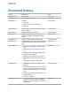
802800U74-AP Document History Document History Version Description Date 6802800U74–A Initial version. July 2006 6802800U74–B Minor changes introduced. August 2006 6802800U74–C Updated: August 2006 • Table 4–4. • Table 4–5 and inserted new note. • Table 5–6. 6802800U74–D Service Cable and Connector Box Description section updated. October 2006 6802800U74–E Updates throughout the manual.
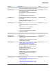
6802800U74-AP Document History Version 6802800U74–M 6802800U74–N 6802800U74–P Description • Other minor updates throughout the manual. • Ethernet Site Link Cabling hardware installation information added. • Ethernet Site Link cabling and interconnection added. • Configuring Ethernet Site Link added. • Ethernet Site Link Retro-fit kit and configurations added. • Added section MTS LVD Kit Installation to Hardware Installation chapter. Updated: • With 260 MHz additions throughout the manual.
6802800U74-AP Document History Version Description • Service Cable and Connector Box Description on page 244. • Setting Base Radio IP on page 256.Station Verification Procedures on page 260. • Added Configuring the Base Radio VSWR on page 258. • Verifying the Base Radio Receiver Parameters in BR-Arch-1 Architecture on page 257. • XHUB Controller – Front Panel Indicators (LED) on page 341. • XHUB Controller – Front Panel Connectors on page 342.
6802800U74-AP Document History Version Description • Field Replaceable Units for MTS LiTE on page 478. • Field Replaceable Units for MTS 2 on page 480. • Field Replaceable Units for MTS 4 on page 483. • Miscellaneous Troubleshooting on page 427. Date 6802800U74–AC Updated RF Cabling – MTS 4, No Diversity on page 204. July 2014 6802800U74–AD Added: September 2014 • Resetting the RTC Battery Status on page 332.
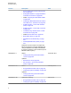
6802800U74-AP Document History Version Description Date 6802800U74–AJ Updated for DIMETRA X Core. September 2017 6802800U74–AK Updated GPS Site Reference Operation Modes on page 135. January 2018 Added Restriction of Hazardous Substances Compliance on page 428. 6802800U74–AL Updated • GPS Receiver Detailed Troubleshooting on page 384 • Note in Antenna Installation Considerations on page 73.
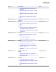
6802800U74-AP Contents Contents Copyrights................................................................................................................... 2 Declaration of Conformity.......................................................................................... 3 CMM Labeling and Disclosure Table.........................................................................4 Service Information.....................................................................................................
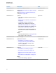
6802800U74-AP Contents 1.7.4 Base Radio Module..................................................................................................56 1.7.4.1 Base Radio Transceiver.............................................................................56 1.7.4.2 Base Radio Power Amplifier...................................................................... 57 1.7.5 Power Supply Unit................................................................................................... 57 1.7.5.
6802800U74-AP Contents 4.3 Cabinet Transportation.......................................................................................................... 91 4.3.1 Transportation Safety Considerations......................................................................91 4.3.2 MTS LiTE and MTS 2 Cabinets Transportation....................................................... 91 4.3.3 Moving the MTS 4 and Expansion Cabinet..............................................................91 4.
6802800U74-AP Contents 4.8.4.1 Remote GPS Receiver Placement Requirements................................... 139 4.8.4.2 Remote GPS Receiver Cabling................................................................140 4.8.5 GPS Antenna Connection......................................................................................142 4.8.5.1 GPS Antenna Line Loss...........................................................................144 4.8.6 GPS Interference Avoidance.....................................
6802800U74-AP Contents 5.4 Ethernet Site Link Cabling................................................................................................... 183 5.4.1 Ethernet Site Link Cabling – MTS LiTE................................................................. 183 5.4.2 Ethernet Site Link Cabling – MTS 2.......................................................................184 5.4.3 Ethernet Site Link Cabling – MTS 4 with Single Site Controller.............................186 5.4.
6802800U74-AP Contents 6.2.3 Service Cable and Connector Box Description......................................................244 6.2.4 Setting Up Service Terminal.................................................................................. 246 6.3 CAN Bus Configuration........................................................................................................247 6.3.1 PSU CAN Bus Commands.................................................................................... 247 6.3.
6802800U74-AP Contents 7.3 MTS 4 RFDS....................................................................................................................... 290 7.3.1 MTS 4 Filter Tray................................................................................................... 291 7.3.2 MTS 4 Preselector................................................................................................. 293 7.3.2.1 Replacing the MTS 4 Preselector...........................................................
6802800U74-AP Contents 9.2.2 XHUB Controller – Rear Panel.............................................................................. 343 9.2.2.1 XHUB Controller – Rear Panel Connectors............................................. 343 9.3 Replacing the XHUB Controller........................................................................................... 343 9.3.1 XHUB Controller – FRU......................................................................................... 344 Chapter 10: Base Radio.
6802800U74-AP Contents 13.1.1 Site Controller Fault Indications........................................................................... 373 13.1.2 LED Fault Indications...........................................................................................373 13.1.2.1 Troubleshooting Flow Chart................................................................... 377 13.1.2.2 Troubleshooting: Power......................................................................... 377 13.1.2.
6802800U74-AP Contents 14.3.9 MTS LiTE / MTS 2 Preselector Specifications..................................................... 438 14.3.10 MTS 4 Duplexer Specifications..........................................................................438 14.3.11 MTS 4 Post Filter Specifications........................................................................ 439 14.3.12 MTS 4 Preselector Specifications...................................................................... 439 14.3.
6802800U74-AP Contents 15.6 Hybrid Combiner Expansion.............................................................................................. 471 15.6.1 Installing an additional Hybrid Combiner............................................................. 471 15.6.2 Configuration........................................................................................................471 15.7 Expansion from MTS 2 to MTS 4 Cabinet.........................................................................
6802800U74-AP List of Figures List of Figures Figure 1: MTS LiTE Cabinet................................................................................................................... 46 Figure 2: MTS 2 Cabinet ....................................................................................................................... 48 Figure 3: MTS 4 Cabinet .......................................................................................................................
6802800U74-AP List of Figures Figure 37: DC Plug MTS 4 (Motorola P/N 3166501A02) – Blue/Black Wires...................................... 111 Figure 38: DC Plug MTS 4 (Motorola P/N 3166501A02) – Red/Black Wires....................................... 111 Figure 39: 100–240 VAC Connection on the MTS LiTE Junction Panel.............................................. 112 Figure 40: 100–240 VAC Connection on the MTS 2 Junction Panel....................................................
6802800U74-AP List of Figures Figure 75: E1/X.21 and Ethernet Site Link Connectors on the MTS LiTE Junction Panel................... 145 Figure 76: E1/X.21 and Ethernet Site Link Connectors on the MTS 2 Junction Panel.........................146 Figure 77: E1/X.21 and Ethernet Site Link Connectors on the MTS 4 Junction Panel.........................146 Figure 78: Site Link Connector E1 Pinout............................................................................................
6802800U74-AP List of Figures Figure 114: RF Cabling Diagram for MTS 4 with No Diversity............................................................. 205 Figure 115: RF Cabling/Connections for MTS 4 with one TX/RX ant. and Up to Two Additional RX ant. ..................................................................................................................................................208 Figure 116: RF Cabling/Connections for MTS 4 with Two TX/RX ant. and Up to One Additional RX ant.............
6802800U74-AP List of Figures Figure 148: MTS 4 TX/RX on two Antennas and up to one RX Antenna Filter Configuration..............292 Figure 149: MTS 4 TX on one Antenna and up to three RX Antennas Filter Configuration................. 292 Figure 150: MTS 4 TX on one Antenna and two RX Antennas Filter Configuration.............................293 Figure 151: MTS 4 TX on one Antenna and three RX Antennas Filter Configuration.......................... 293 Figure 152: MTS 4 Preselector.........................
6802800U74-AP List of Figures Figure 187: MTS LiTE Airflow...............................................................................................................369 Figure 188: MTS 2 Airflow.................................................................................................................... 370 Figure 189: MTS 4 Airflow.................................................................................................................... 371 Figure 190: Site Controller LEDs..............
6802800U74-AP List of Tables List of Tables Table 1: Architecture comparison - boot order and functionalities of bootloaders and applications.......42 Table 2: MTS LiTE Cabinet.................................................................................................................... 46 Table 3: MTS 2 Cabinet..........................................................................................................................48 Table 4: MTS 4 Cabinet..............................................
6802800U74-AP List of Tables Table 31: MTS LiTE, MTS 2, and MTS 4 and Expansion Cabinets Mounting Screws.........................158 Table 32: AC/DC Power Cabling for MTS LiTE....................................................................................163 Table 33: AC/DC Power Cabling for MTS 2......................................................................................... 164 Table 34: AC/DC Power Cabling for MTS 4............................................................................
6802800U74-AP List of Tables Table 65: RF Cabling/Connections for Expansion Cabinet with Two TX ant. and Up to Three Additional RX ant.............................................................................................................................225 Table 66: CAN Bus Cabling for MTS LiTE........................................................................................... 228 Table 67: CAN Bus Cabling for MTS 2 with TX/RX on 1 ant. RX on 2 ant...........................................
6802800U74-AP List of Tables Table 104: Site Controller LED Fault Indications .................................................................................373 Table 105: Site Reference States – status sc...................................................................................... 378 Table 106: Site Reference Reasons.....................................................................................................378 Table 107: Site Reference States – status bts..............................
6802800U74-AP List of Tables Table 143: Available FRUs for MTS 2.................................................................................................. 480 Table 144: Other FRUs for MTS 2 Available from After Market Operations (AMO)............................. 480 Table 145: Available FRUs for MTS 4..................................................................................................
6802800U74-AP List of Processes List of Processes Installation Prerequisites ....................................................................................................................... 90 Installing the Cabinet Using the Mounting Plate ....................................................................................97 Performing a Final Check-Out after Installation ...................................................................................154 Preparing for Configuration and Testing .
6802800U74-AP List of Procedures List of Procedures Receiving the MTS Equipment .............................................................................................................. 89 Moving the MTS 4 and Expansion Cabinet ........................................................................................... 91 Installing the Cabinet Using the Mounting Brackets .............................................................................. 95 Installing the Mounting Plate ....................
6802800U74-AP List of Procedures Setting Up the Equipment for Receiver Verification ............................................................................ 265 Verifying the Receiver ......................................................................................................................... 265 Verifying and Tuning the Receiver RSSI Levels ..................................................................................
6802800U74-AP List of Procedures Replacing the XHUB Controller ........................................................................................................... 343 Removing the Base Radio ...................................................................................................................355 Reinstalling the Base Radio ................................................................................................................ 356 Removing the Power Supply Unit (PSU) ...........
6802800U74-AP About MTS LiTE, MTS 2 and MTS 4 Installation, Configuration and Basic Service Manual About MTS LiTE, MTS 2 and MTS 4 Installation, Configuration and Basic Service Manual This manual provides an overview of the Motorola Transceiver Station (MTS) within the DIMETRA System.
6802800U74-AP About MTS LiTE, MTS 2 and MTS 4 Installation, Configuration and Basic Service Manual Document Title Description ded to comprehend the theory of operation and it provides equipment/subsystem functional descriptions.
6802800U74-AP About MTS LiTE, MTS 2 and MTS 4 Installation, Configuration and Basic Service Manual • EN 61000-3-3 standard for Electromagnetic compatibility (EMC) -- Part 3-3 Limits - Limitation of voltage changes, voltage fluctuations, and flicker in public low-voltage supply systems, for equipment with rated current =16 A per phase and not in subject to conditional connection. NOTICE: This is a Class A product.
6802800U74-AP Icon Conventions Icon Conventions The documentation set is designed to give the reader more visual clues. The following graphic icons are used throughout the documentation set. DANGER: The signal word DANGER with the associated safety icon implies information that, if disregarded, will result in death or serious injury. WARNING: The signal word WARNING with the associated safety icon implies information that, if disregarded, could result in death or serious injury, or serious product damage.
6802800U74-AP Style Conventions Style Conventions The following style conventions are used: Convention Description Bold This typeface is used for names of, for instance, windows, buttons, and labels when these names appear on the screen (example: the Alarms Browser window). When it is clear that we are referring to, for instance, a button, the name is used alone (example: Click OK).
6802800U74-AP Chapter 1: MTS Overview Chapter 1 MTS Overview Motorola Transceiver Station (MTS) is a Base Station of a DIMETRA communication system. A Base Station serves as the Radio Frequency (RF) interface between the system infrastructure and the mobile stations.
6802800U74-AP Chapter 1: MTS Overview BR-Arch-1 boot process POLO(release) ver. MTS_BRC_BOOT1-R08.40.02 FEATURES flash telnetd testapp auxcmds /tftp /gzip dns boardparam Local Ethernet address......00:25:F1:28:DF:D2 Local Ethernet address......00:25:F1:28:DF:D3 DNS resolver not configured. These are the boot parameters: autoboot...............yes boot timeout...........5 seconds boot method 1.......... boot method 2.......... boot method 3.......... boot method 4..........
6802800U74-AP Chapter 1: MTS Overview BR-Arch-2 boot process U-Boot MTS_BRC_UBOOT-R08.44.03 (Nov 20 2015 - 21:43:13) CPU0: P1021E, Version: 1.1, (0x80ec0111) Core: E500, Version: 5.1, (0x80212051) Clock Configuration: CPU0:533.333 MHz, CPU1:533.333 MHz, CCB:266.667 MHz, DDR:333.333 MHz (666.667 MT/s data rate) (Asynchronous), LBC:66.667 MHz QE:133.
6802800U74-AP Chapter 1: MTS Overview ### Starting Tetra Application ### ### Press Enter ### username: Downloading configuration file (brc01.cf.2)... SUCCESS NOTICE: BR Application is started, BR offers call services now, you can log in. username: *** password: *** *** You are now logged in with Factory access *** BR) 1.2 MTS Platform Description The MTS provides the interface between the mobile stations within the DIMETRA system and the rest of the system infrastructure.
6802800U74-AP Chapter 1: MTS Overview NOTICE: When an MTS LiTE is managed in TESS application, MTS 2 should be selected. For information regarding Network Management configuration of the MTS, see the “MTS Site Object” sections of the Zone Configuration Manager manual and Online Help. 1.
6802800U74-AP Chapter 1: MTS Overview Callout Number Description 3 Duplexer 4 Preselector 5 Site Controller 6 Base Radio 7 Fan Tray 8 Power Supply Unit The modules that comprise a typical configuration MTS LiTE cabinet includes the following modules: • Duplexer • Preselector • Site Controller • Base Radio • Power Supply Unit The door of the cabinet has a lock to prevent unauthorized opening. Unauthorized opening of the door generates an alarm.
6802800U74-AP Chapter 1: MTS Overview Figure 2: MTS 2 Cabinet 1 2 3 8 4 7 6 5 Table 3: MTS 2 Cabinet Callout Number Description 1 Preselectors 2 Junction Panel 3 HC 4 TSC 5 Fan Tray 48
6802800U74-AP Chapter 1: MTS Overview Callout Number Description 6 PSU 7 BRs 8 Duplexer The modules that comprise the MTS 2 cabinet vary based on the type of configuration chosen. A typical configuration includes the following modules: • Duplexer • Preselector • Hybrid Combiner • Site Controller • Base Radio(s) • Power Supply Unit The door of the cabinet has a lock to prevent unauthorized opening. Unauthorized opening of the door generates an alarm.
6802800U74-AP Chapter 1: MTS Overview Figure 3: MTS 4 Cabinet 2 1 3 4 5 6 7 8 9 10 11 12 Table 4: MTS 4 Cabinet Callout Number Description 1 Antenna Connectors 2 Junction Panel 3 Filter Section 4 Cavity Combiners 5 BRs 6 PSU 7 SC 50
6802800U74-AP Chapter 1: MTS Overview Callout Number Description 8 Fan Tray 9 BRs 10 PSU 11 SC 12 Fan Tray The modules that comprise the MTS 4 cabinet vary based on the type of configuration chosen.
6802800U74-AP Chapter 1: MTS Overview Figure 4: MTS Expansion Cabinet Junction Panel Filter Section (RX Splitters) Cavity Combiners Cavity Conjunction Hole (on each side of Cabinet) BRs PSU XHUB Fan Tray BRs PSU XHUB Fan Tray Table 5: MTS Expansion Cabinet Callout Number Description 1 Junction Panel 2 Filter Section (RX Splitters) 3 Cavity Combiners 4 Cavity Conjunction Hole (on each side of Cabinet) 5 BRs 6 PSU 52
6802800U74-AP Chapter 1: MTS Overview Callout Number Description 7 XHUB 8 Fan Tray 9 BRs 10 PSU 11 XHUB 12 Fan Tray The modules that comprise the Expansion Cabinet vary based on the type of configuration chosen. A typical configuration includes the following modules: • RX Splitter(s) • Cavity Combiner(s) • eXpansion HUB (XHUB) • Base Radios • Power Supply Unit(s) The door of the cabinet has a lock to prevent unauthorized opening. Unauthorized opening of the door generates an alarm.
6802800U74-AP Chapter 1: MTS Overview • Hybrid Combiner (HC) (MTS 2 and MTS 4 Prime Cabinet only) • Rx Splitter (Expansion Cabinet Only) NOTICE: The Preselector types and Duplexer types used in MTS LiTE and MTS 2 are different from the types used in MTS 4. 1.7.1.1 Preselector The Preselector is a bandpass filter, which allows only the receiver signals to pass. The Preselector incorporates a Receiver Multicoupler (RMC).
6802800U74-AP Chapter 1: MTS Overview MTS Frequency Bandwidth Duplex Spacing transmitter frequency being higher. 800 MHz 19 MHz Duplex spacing between a transmitter frequency and the corresponding receive frequency is 45 MHz. 900 MHz 5 MHz Duplex spacing between a transmitter frequency and the corresponding receive frequency is 15 MHz. 1.7.1.3 Post Filter A Post Filter consist of one bandpass filter which allows the transmitter signal to pass.
6802800U74-AP Chapter 1: MTS Overview The following table shows the frequency range covered by various Hybrid Combiners. Table 8: Hybrid Combiner — Frequency Range Hybrid Combiner Frequency Range 260 MHz 260 MHz — 275 MHz 400 MHz 350 MHz — 470 MHz 800 MHZ 850 MHz — 870 MHz 900 MHz 932 MHz — 942 MHz 1.7.1.
6802800U74-AP Chapter 1: MTS Overview 1.7.4.2 Base Radio Power Amplifier The Power Amplifier (PA) in conjunction with the exciter provides the transmitter functions for the Base Radio. The PA accepts the low-level modulated RF signal from the exciter and amplifies the signal for transmission through the RF output connector. 1.7.5 Power Supply Unit Depending on the configuration, the MTS includes one or two Power Supply Units (PSUs).
6802800U74-AP Chapter 2: General Safety Chapter 2 General Safety This chapter summarizes the safety-related information that you should both understand and observe when working with Motorola Transceiver Stations (MTS). In addition to the information contained in this chapter, additional safety-related information can be found in other parts of the document. IMPORTANT: This is not an exhaustive list of all the precautions and safety measures.
6802800U74-AP Chapter 2: General Safety CAUTION: Antenna design is the customers responsibility. All aspects of antenna design must comply with the relevant local regulations. CAUTION: Familiarize yourself with Man-Machine Interface (MMI) commands and their usage before performing procedures in this documentation. Improperly applying MMI commands can result in equipment damage.
6802800U74-AP Chapter 2: General Safety In order to ensure optimal communication performance and compliance with applicable RF exposure limits, it is recommended that the antenna is installed outside the building hosting this equipment, on the roof or on a tower if at all possible.
6802800U74-AP Chapter 2: General Safety WARNING: Burn hazard. The metal housing of the product may become extremely hot. Use caution when working around the equipment. Figure 5: Warning Label on Hot Modules WARNING: DC input voltage must be no higher than 60 VDC. This maximum voltage includes consideration of the battery charging "float voltage" associated with the intended supply system, regardless of the marked power rating of the equipment. Failure to follow this guideline may result in electric shock.
6802800U74-AP Chapter 2: General Safety WARNING: Special precautions are required when handling batteries: 62 • To avoid spilling acid, do not tip batteries. • Battery acid can cause severe burns and blindness if it comes into contact with skin or eyes. Wash affected skin or eyes immediately with running water. Seek medical help immediately. • Jewelry should not be worn while working with batteries. • Installation personnel should wear necessary safety equipment when installing batteries.
6802800U74-AP Site Preparation Chapter 3 Site Preparation Before performing the MTS installation tasks, various considerations such as site planning or environmental requirements need to be taken into account. 3.1 Site Planning Proper planning helps to prevent potential on-site and off-site interference from other RF systems, and helps maximize system performance. To minimize the cabling lengths between RF equipment, plan site layouts.
6802800U74-AP Chapter 3: Site Preparation • Suitability, space availability, and location of the existing cable tray or ladder rack between the equipment room and the antenna tower or the antenna system support structure. • Cable access route into the equipment room check • Type of tower and the type of structure on which the GPS antenna will be mounted 3.1.
6802800U74-AP Chapter 3: Site Preparation 3.2 Cabinets Installation Considerations The equipment cabinets are not approved or intended for outdoor use. 3.2.1 MTS LiTE Cabinet Considerations The equipment cabinet dimensions are: 450 mm (width)/480 mm (depth)/380 mm (height) as shown in the following figure.
6802800U74-AP Chapter 3: Site Preparation Figure 7: Suggested MTS LiTE Site Layout HVAC HVAC minimum 600mm Service Area rack MTS LiTE rack minimum 800mm 427mm minimum 45mm 3.2.2 MTS 2 Cabinet Considerations The equipment cabinet dimensions are: 443 mm (width)/472 mm (depth)/605 mm (height) as shown in the following figure.
6802800U74-AP Chapter 3: Site Preparation Figure 8: MTS 2 Cabinet Dimensions 605 mm 443 mm 472 mm The equipment cabinet may be installed against adjacent equipment, however the following minimal distances must be retained: • 45 mm on both sides of the cabinet • 800 mm of free space in front of the cabinet The cabinet front door is removable. Figure 9: Suggested MTS 2 Site Layout on page 68 shows the cabinet layout within a suggested site.
02800U74-AP Chapter 3: Site Preparation rack MTS2 rack 472mm. HVAC Service Area minimum 800m. HVAC minimum 600m. Figure 9: Suggested MTS 2 Site Layout minimum 45mm. 3.2.3 MTS 4 Cabinet Considerations The equipment cabinet dimensions are: 550 mm (width)/570 mm (depth)/1430 mm (height) as shown in the following figure.
6802800U74-AP Chapter 3: Site Preparation Figure 10: MTS 4 Cabinet Dimensions 1430 mm 570 mm 550 mm 69
6802800U74-AP Chapter 3: Site Preparation The equipment cabinet may be installed against adjacent equipment, however the following minimal distances must be retained: • 25 mm on both sides of the cabinet • 800 mm of free space in front of the cabinet The cabinet front door has hinges on both sides and it can be opened right, left, or removed. Figure 11: Suggested MTS 4 Site Layout on page 70 shows the cabinet layout within a suggested site.
6802800U74-AP Chapter 3: Site Preparation Figure 12: Expansion Cabinet Dimensions 71
6802800U74-AP Chapter 3: Site Preparation The equipment cabinet may be installed against adjacent equipment, however the following minimal distances must be retained: • 25 mm on both sides of the cabinet • 800 mm of free space in front of the cabinet The cabinet front door has hinges on both sides and it can be opened right, left, or completely removed. Figure 13: Suggested Expansion Cabinet Site Layout on page 72 shows the cabinet layout within a suggested site.
6802800U74-AP Chapter 3: Site Preparation 3.3 Antenna Installation Considerations When planning site for the RF system, consider proper antennas placement. For full instructions and guidelines, see the Motorola Standards and Guidelines for Communications Sites, R56 manual. RF Antenna Place the MTS equipment near to the existing cable tray or ladder rack for RF cabling. GPS Antenna Mount the GPS antenna below the tallest point on the tower, pole, or roof of the MTS site.
6802800U74-AP Chapter 3: Site Preparation Hazardous Materials and Equipment Compliance with all local and any other regulations concerning the handling and use of hazardous materials and equipment is the sole responsibility of the customer and associated agents. Seismic Active Areas The MTS operating in seismic active areas may require additional bracing of the equipment cabinet. 3.6 Environmental Considerations When planning the MTS site, carefully consider the environment in which the MTS operates.
6802800U74-AP Chapter 3: Site Preparation Air Quality Considerations For cabinet-mounted equipment operating in an area without environmental control, the airborne particulates level must not exceed concentration defined in ETSI norm EN300 019 1-3 Class 3. Salt mist like sea salt and road salt is excluded and shall always be avoided. 3.
6802800U74-AP Chapter 3: Site Preparation • AC operation (within 90 VAC to 264 VAC; 45 Hz to 66 Hz) and switch over to DC backup operation when AC failed The PSU handles the automatic switch over to a backup battery in the event of AC mains failure. CAUTION: An external disconnect device and appropriate 20A fuse are required on the DC power supply line.
6802800U74-AP Chapter 3: Site Preparation AC When Charg ing (W) Heat AC When Charging (W) DC -48 V (W) Heat DC (W) MTS 400 MHz Configuration AC (W) Heat AC (W) MTS2 with 2 BRs w. Hybrid 295 275 675 330 285 265 Low power PA, no fans MTS4 with 1 BR w. MTCC/ATCC 240 230 625 290 235 225 Low power PA, fans MTS4 with 2 BRs w. MTCC/ATCC 375 355 755 410 365 345 Low power PA, fans MTS4 with 3 BRs w. MTCC/ATCC 620 590 1380 705 605 575 Low power PA, fans MTS4 with 4 BRs w.
6802800U74-AP Chapter 3: Site Preparation MTS 400 MHz Configuration AC (W) MTS4 with 4 BRs w.
6802800U74-AP Chapter 3: Site Preparation Heat AC (W) AC When Charg ing (W) Heat AC When Charging (W) DC -48 V (W) Heat DC (W) MTS 400 MHz Configuration AC (W) MTS4 with 3 BRs w. MTCC/ATCC 103 5 960 1800 1075 101 0 935 Fans MTS4 with 4 BRs w. MTCC/ATCC 132 0 1220 2080 1330 129 0 1190 Fans MTS2 with 1 BR 355 315 735 385 345 305 No combining, fans MTS2 with 2 BRs 595 515 975 385 580 500 Two TX ant., no combining.
6802800U74-AP Chapter 3: Site Preparation MTS 800 MHz Configuration AC (W) Heat AC (W) AC When Charg ing (W) Heat AC When Charg ing (W) DC-48 V (W) Heat DC (W) Comment MTS4 with 3 BRs w. MTCC/ATCC 655 625 1420 740 640 610 Fans MTS4 with 4 BRs w. MTCC/ATCC 810 770 1575 885 795 755 Fans MTS2 with 1 BR 280 255 660 310 270 245 No combining, fans MTS2 with 1 BR w.
6802800U74-AP Chapter 3: Site Preparation Expansion Cabinet Consumptions MTS 400 MHz Configuration AC (W) Heat AC (W) AC When Charg ing (W) Heat AC When Charging (W) DC -48 V (W) Heat DC (W) MTS4 Exp. Cab. w. 3 BRs w. MTCC/ATCC 620 590 1380 705 605 575 Low power PA, fans MTS4 Exp. Cab. w. 4 BRs w. MTCC/ATCC 760 720 2005 835 745 705 Low power PA, fans Comment TETRA TX 25 W and TEDS TX 10 W MTS4 Exp. Cab. w. 1 BR w.
6802800U74-AP Chapter 3: Site Preparation Expansion Cabinet Consumptions MTS 400 MHz Configuration AC (W) Heat AC (W) AC When Charg ing (W) Heat AC When Charging (W) DC -48 V (W) Heat DC (W) MTS4 Exp. Cab. w. 1 BR w. MTCC/ATCC 375 350 755 410 365 340 Fans MTS4 Exp. Cab. w. 2 BRs w. MTCC/ATCC 640 590 1020 645 625 575 Fans MTS4 Exp. Cab. w. 3 BRs w. MTCC/ATCC 103 5 960 1800 1075 101 0 935 Fans MTS4 Exp. Cab. w. 4 BRs w.
6802800U74-AP Chapter 3: Site Preparation Expansion Cabinet 800 MHz Configuration AC (W) Heat AC (W) AC When Charging (W) Heat AC When Charging DC-48 V (W) Heat DC (W) Comment MTS4 Exp. Cab. w. 2 BRs w. MTCC/ATCC 640 590 1020 650 625 575 Fans MTS4 Exp. Cab. w. 3 BRs w. MTCC/ATCC 1040 965 1800 1080 1015 940 Fans MTS4 Exp. Cab. w. 4 BRs w. MTCC/ATCC 1320 1220 2085 1335 1290 1190 Fans 3.7.2.1.
6802800U74-AP Chapter 3: Site Preparation MTS 260 MHz Configuration AC (W) Heat AC (W) MTS2 with 2 BRs 430 380 AC When Charg ing (W) Heat AC When Charging (W) DC -48 V (W) Heat DC (W) 810 470 420 370 Comment Two TX ant., low power PA NOTICE: • All the values in the table are calculated from AC = 230 V • Add additional 5% for 110 V • Charging is up to 6 A per PSU 3.7.2.1.
6802800U74-AP Chapter 3: Site Preparation 3.7.2.1.5 Power Loads and Heat Dissipation – MTS 800 MHz / 900 MHz Table 17: Typical Power Loads and Heat Dissipation Values – MTS 800 MHz / 900 MHz Configuration AC (W) Heat AC (W) AC When Charg ing (W) Heat AC When Charging (W) DC -48 V (W) Heat DC (W) MTS LiTE and MTS2 with 1 BR 280 270 660 325 215 205 No combining, high power PA, fans MTS2 with 1 BR w.
6802800U74-AP Chapter 3: Site Preparation MTS 800 MHz/ 900 MHz Configuration AC (W) MTS4 with 4 BRs w. MTCC/ATCC 144 5 Heat AC (W) AC When Charg ing (W) Heat AC When Charging (W) DC -48 V (W) 1345 2205 1515 141 0 Heat DC (W) 1310 Comment High power PA, fans NOTICE: • All the values in the table are calculated from AC = 230 V • Add additional 5% for 110 V • Charging is up to 6 A per PSU 3.7.2.1.
6802800U74-AP Chapter 3: Site Preparation 3.7.2.2 AC and DC Current Load WARNING: The MTS has a 2mA minimum power consumption even when the Power Supply Unit (PSU) is switched off. The switch only disconnects DC outputs and charging currents. In case of the field repair, disconnect all PSU connecting cables. 3.7.2.3 Backup Battery The backup battery is normally located near the cabinet(s).
6802800U74-AP Chapter 3: Site Preparation Figure 14: Opto-isolated Alarm Input Structure Schmitt Trigger Alarm Indication Vsupply 12VDC RC Filter Opto-Isolator Debounce / Noice Rejection Contact Closure (External to Alarm Card) 3.9 Grounding Requirements WARNING: The MTS site must meet certain specifications for adequate protection from lightning induced transients. Proper ground installation methods are outlined in the Motorola Standards and Guidelines for Communications Sites, R56.
6802800U74-AP Hardware Installation Chapter 4 Hardware Installation MTS hardware installation includes mounting the equipment, installing cables, and establishing connections for the input power, antennas, and site link interfaces. 4.1 Installation Overview The MTS cabinets can be mounted in two ways: • Directly to the floor using the mounting brackets • Using the mounting plate MTS LiTE, MTS 2, MTS 4, and the Expansion Cabinet all have four mounting holes for leveling feet.
6802800U74-AP Chapter 4: Hardware Installation 2 Check the MTS equipment against the itemized packing list. 3 If available, check the sales order with the packing list to account for all equipment ordered. NOTICE: Contact your Motorola Solutions representative to report the missing items and for additional information. 4 Check for loose or damaged equipment. 5 Check all sides of the Base Stationcabinet for dents, scratches, or other damage.
6802800U74-AP Chapter 4: Hardware Installation 4.3 Cabinet Transportation To move and locate all the equipment to the final position, employ a transportation company specializing in heavy electronic equipment transport. 4.3.1 Transportation Safety Considerations WARNING: Crush hazard could result in personal injury or equipment damage. MTS LiTE cabinet with packaging can weigh up to 49 kg, MTS 2 cabinet with packaging up to 64 kg and MTS 4 cabinet with packaging up to 170 kg.
6802800U74-AP Chapter 4: Hardware Installation 3 Tighten the screws to 10-13.5 Nm (91-120 in-lbs) torque. 4 Lift the cabinet from a center point, keep the minimum distance of 350 mm between the lifting point and the top surface of the cabinet to ensure the proper lifting angle. The lifting brackets may fail if the distance is shorter. Figure 15: Lifting Point for MTS 4 and Expansion Cabinet minimum 350mm 5 Put the MTS cabinet back on the floor, in the vertical or horizontal position.
6802800U74-AP Chapter 4: Hardware Installation Figure 16: Placing the MTS 4 and the Expansion Cabinet in the Vertical or Horizontal Position 93
6802800U74-AP Chapter 4: Hardware Installation 4.4 Cabinet Installation Depending on the MTS type, installing the MTS cabinet within a site may include wall fixing or floor fixing. IMPORTANT: To enable service access and assure the passive cooling ventilation, the free space above the cabinet must be 20 cm at minimum The antenna cabling may require additional space. Allow at least 80 cm of floor space in front of the cabinet to permit access during installation.
6802800U74-AP Chapter 4: Hardware Installation Figure 17: MTS – Mounting Brackets 4.4.3 Installing the Cabinet Using the Mounting Brackets When and where to use: Perform this procedure to properly install the cabinet within the site facility using the mounting brackets.
6802800U74-AP Chapter 4: Hardware Installation drilled. The front brackets can be placed anywhere around the leveling feet at a radius of 60 mm or 105 mm (either hidden under the cabinet, or stuck out for easy mounting), see the circles in Figure 18: MTS LiTE / MTS 2 – Drill Hole Position for the Mounting Brackets on page 96 and Figure 19: MTS 4 and Expansion Cabinet – Drill Hole Position for the Mounting Brackets on page 96.
6802800U74-AP Chapter 4: Hardware Installation 5 Move the MTS cabinet near to the mounting brackets. 6 Move the MTS backwards ensuring that the rear leveling feet of the MTS locate in the corresponding cups in the rear mounting brackets. 7 Push the front brackets over the corresponding leveling feet and swing them until they engage the screws. 8 Fully tighten the screws in the front brackets, see the following figure. Figure 20: MTS – Mounting Brackets and the Cabinet 4.4.
6802800U74-AP Chapter 4: Hardware Installation Figure 21: MTS Mounting Plate The mounting plate is normally secured directly to the floor. NOTICE: The use of an insulated base may be considered where additional lightning protection is required or where local regulations require this (see R56 Manual for further information). 4.4.4.2 Installing the Mounting Plate When and where to use: Perform this procedure to properly install the mounting plate within the site facility.
6802800U74-AP Chapter 4: Hardware Installation 2 Use the mounting plate as drilling template or mark the floor according to the dimensions shown in Figure 22: MTS LiTE/MTS 2 – Drill Hole Position for the Mounting Plate on page 99 and Figure 23: MTS 4 – Drill Hole Position for the Mounting Plate on page 99. Remember to keep the 13 mm distance behind the mounting plate. Four 12 mm holes are pre-drilled. Additional holes may be drilled in the mounting plate where required.
6802800U74-AP Chapter 4: Hardware Installation 2 Bring the MTS in position and lower it onto the mounting plate. Care must be taken not to lower the MTS onto the locating tabs on the rear of the mounting plate to avoid bending. 3 Move the MTS from the front to the back ensuring that the leveling feet of the MTS locate in the corresponding slots in the mounting plate. 4 Secure the MTS on the mounting plate using the two front security M10 screws.
6802800U74-AP Chapter 4: Hardware Installation Figure 25: MTS – Wall Fixing 500 M6 NOTICE: Use brackets and screws appropriate for the site wall properties. 4.5 Electrical Connections NOTICE: Battery backup systems are not manufactured by Motorola Solutions. Consult the manufacturers instruction manual and other pertinent documentation for installing battery systems. Any local regulations shall be adhered to when installing battery equipment.
6802800U74-AP Chapter 4: Hardware Installation 4.5.1 Grounding Connection Various cabling from the equipment cabinet to external equipment is made through the MTS Junction Panel located at the top-rear of the equipment cabinet. The Junction Panel is accessed from the top of the cabinet. NOTICE: Depending on system configuration, not all connector locations on Junction Panel are populated. Cabinet grounding wires may have been installed prior to the cabinet installation.
6802800U74-AP Chapter 4: Hardware Installation Figure 26: Station Ground Point on the MTS LiTE Junction Panel Figure 27: Station Ground Point on the MTS 2 Junction Panel 103
6802800U74-AP Chapter 4: Hardware Installation Figure 28: Station Ground Point on the MTS 4 Junction Panel Figure 29: Station Ground Point on the Expansion Cabinet Junction Panel 4.5.2 Grounding the Equipment Cabinet To protect the equipment against lightning induced surges, install the cabinet grounding wires to the MTS cabinet. Procedure: 1 Strip the end of the wire to be connected to the station ground point in the junction panel.
6802800U74-AP Chapter 4: Hardware Installation Figure 30: Cabinet Grounding 4 Using the M10 bolt provided, secure the cabinet ground wire to the M10 nut on the junction panel. 5 Ground connections should be checked after installation. See Recommended Torque on page 157. 4.5.2.1 Battery System Grounding Ground the battery cabinet (if used) in accordance with manufacturers instructions and any applicable local regulations. 4.5.2.
6802800U74-AP Chapter 4: Hardware Installation 4.5.3.1 -48 VDC Input Power and Backup Battery Charging Connections The -48 VDC connectors are used for: • Supplying the MTS with power in the DC only mode – in DC only mode the MTS takes the power from a separate -48 VDC facility power system • For charging backup batteries in the AC mode CAUTION: An external disconnect device is required on the DC power supply line.
6802800U74-AP Chapter 4: Hardware Installation Figure 31: -48 VDC Connection on the MTS LiTE Junction Panel 107
6802800U74-AP Chapter 4: Hardware Installation Figure 32: -48 VDC Connection on the MTS 2 Junction Panel Figure 33: -48 VDC Connections on the MTS 4 Junction Panel 108
6802800U74-AP Chapter 4: Hardware Installation Figure 34: -48 VDC Connections on the Expansion Cabinet Junction Panel 4.5.3.2 Connecting -48 VDC Power Source to the Equipment Cabinet Procedure: 1 WARNING: Make sure that all power is off to prevent accidental contact with high voltage and injury to personnel. 2 Route two runs of bulk wiring between the MTS DC input connector and the facility power supply -48 VDC connections.
6802800U74-AP Chapter 4: Hardware Installation Figure 35: DC Plug MTS LiTE/MTS 2 (Motorola P/N 3166501A01) – Blue/Black Wires Plug the blue wire into negative as shown in the picture. Figure 36: DC Plug MTS LiTE/MTS 2 (Motorola P/N 3166501A01) – Red/Black Wires Plug the red wire into positive as shown in the picture.
6802800U74-AP Chapter 4: Hardware Installation Figure 37: DC Plug MTS 4 (Motorola P/N 3166501A02) – Blue/Black Wires Plug blue wires into negative as shown in the picture. Figure 38: DC Plug MTS 4 (Motorola P/N 3166501A02) – Red/Black Wires Plug red wires into positive as shown in the picture. 5 Connect the other end of wires to -48 VDC output in accordance with manufacturers instructions and any applicable local regulations. 6 The MTS DC plug shall be fixed to the DC connector using the plugs screws. 4.
6802800U74-AP Chapter 4: Hardware Installation 4.5.3.3 100–240 VAC Input Power Connections NOTICE: Figure 40: 100–240 VAC Connection on the MTS 2 Junction Panel on page 113 and Figure 41: 100–240 VAC Connections on the MTS 4 Junction Panel on page 113 depict the newer version of the MTS Junction Panel. There may be small differences in older configurations.
6802800U74-AP Chapter 4: Hardware Installation Figure 40: 100–240 VAC Connection on the MTS 2 Junction Panel Figure 41: 100–240 VAC Connections on the MTS 4 Junction Panel 113
6802800U74-AP Chapter 4: Hardware Installation Figure 42: 100–240 VAC Connections on the Expansion Cabinet Junction Panel 4.5.3.4 Connecting 100–240 VAC Power Source to Equipment Cabinet WARNING: Make sure all power to the Power Supply Unit is switched off to prevent accidental contact with high energy and injury to personnel. Procedure: 1 Connect the AC cable to the AC socket (type IEC C15 line socket, Motorola P/N 3166502A01), which is provided with the MTS.
6802800U74-AP Chapter 4: Hardware Installation Figure 43: AC Socket (IEC Connector) 3 Connect the other end of the AC cable to the facility AC outlet.
6802800U74-AP Chapter 4: Hardware Installation 4.5.3.5 Backup Battery Sensor Connections Figure 44: Backup Battery Sensor Connection on MTS LiTE Junction Panel NOTICE: Figure 45: Backup Battery Sensor Connection on MTS 2 Junction Panel on page 117 and Figure 46: Backup Battery Sensor Connections on MTS 4 Junction Panel on page 117 depict the newer version of the MTS Junction Panel. There may be small differences in older configurations.
6802800U74-AP Chapter 4: Hardware Installation Figure 45: Backup Battery Sensor Connection on MTS 2 Junction Panel Figure 46: Backup Battery Sensor Connections on MTS 4 Junction Panel 117
6802800U74-AP Chapter 4: Hardware Installation Figure 47: Backup Battery Sensor Connections on Expansion Cabinet Junction Panel 4.5.3.6 Connecting the Backup Battery Sensor to the Equipment Cabinet WARNING: Make sure all power to the Power Supply Unit is off to prevent accidental contact with high energy and injury to personnel. NOTICE: Ensure that all the battery temperature sensor cables are fitted into the battery associated with the appropriate PSUs.
6802800U74-AP Chapter 4: Hardware Installation Figure 48: Backup Battery Temperature Sensor Cable 1 Connect to junction panel 2 Connect to backup batteries rack 2 Make AC cable connection between the facility AC outlet and AC connector on the junction panel using plug (Motorola P/N 3166502A01 for MTS LiTE/MTS 2 and Motorola P/N 3166502A02 for MTS 4) as described in 100–240 VAC Input Power Connections on page 112.
6802800U74-AP Chapter 4: Hardware Installation Figure 49: MTS LVD Kit Relay Connection Diagram – Single PSU 1 To DC Main circuit breaker 2 Connect to Power outlet on Site Controller 3 Power Supply 48 VDC 1 LVD G9EA 2 3 -E1.1 120 -E1.2 -E1.3 -E1.
6802800U74-AP Chapter 4: Hardware Installation Figure 50: MTS LVD Kit Relay Connection Diagram – Dual PSU, Dual Batteries A To PSU 1 1 Connect to Power 1 on Site Controller 1 2 To DC Main circuit breaker 5 Power Supply 48 VDC B To PSU 2 3 To DC Main circuit breaker 4 Connect to Power 2 on Site Controller 1 or Power 1 on Site Controller 2 5 Power Supply 48 VDC A B 2 LVD G9EA 3 LVD G9EA 1 4 5 5 -E1.4 -E1.3 -E1.2 -E1.1 -E1.1 -E1.2 -E1.3 -E1.
6802800U74-AP Chapter 4: Hardware Installation Figure 51: MTS LVD Kit Relay Connection Diagram – Dual PSU, Single Battery A To PSU 1 1 Connect to Power 1 on Site Controller 1 2 To DC Main circuit breaker B To PSU 2 3 To DC Main circuit breaker 4 Connect to Power 2 on Site Controller 1 or Power 1 on Site Controller 2 5 Power Supply 48 VDC A B 2 LVD G9EA 3 LVD G9EA 1 4 5 -E1.1 -E1.2 -E1.3 -E1.
6802800U74-AP Chapter 4: Hardware Installation b Two spare Ø6 terminals for 16 mm2 cable are included. Special crimp tool applies on fitting these (not included). c Click the protection cap on. Additional break away windows are available on cap allowing multiple entry of cables. NOTICE: Make sure no damage are done on cables by sharp edges on the cap. d Check that cables are secured properly and tighten the included cable tie retainers. WARNING: Be very careful not to short circuit the battery poles.
6802800U74-AP Chapter 4: Hardware Installation Figure 54: MTS LVD Kit Backplate Plugs 5 Mount the LVD housing to the intended location, i.e. on top of the MTS as shown in Figure below, using a hammer for snapping in the screw. Figure 55: Mounting the MTS LVD Kit NOTICE: The plug fits into any Ø7 mm hole. Center diameter between the two rivet plugs is 90 mm. 6 Locate the Power connector on the Site Controller and disconnect this.
6802800U74-AP Chapter 4: Hardware Installation 4.6 RF Antenna Connections In the MTS 2, the RF antenna connectors are placed on the junction panel, see Figure 56: Base Radio Antenna Connections – MTS LiTE on page 125, Figure 57: Base Radio Antenna Connections – MTS 2 on page 126 and Figure 58: Base Radio Antenna Connections – MTS 2 Non Duplexed on page 127.
6802800U74-AP Chapter 4: Hardware Installation Figure 57: Base Radio Antenna Connections – MTS 2 RX/TX2 or RX2 126 RX3 RX/TX1 or RX1
6802800U74-AP Chapter 4: Hardware Installation Figure 58: Base Radio Antenna Connections – MTS 2 Non Duplexed RX1 RX2 TX 127
6802800U74-AP Chapter 4: Hardware Installation Figure 59: Base Radio Antenna Connections – MTS 4 RX1/TX1 or TX1 RX1 RX3 RX2/TX2 or TX2 RX2 The antenna leads should be dropped above the MTS cabinet as per the site plan. It is assumed that the Base Radio antennas have been installed before and that the RFDS section is properly configured. (If required, refer to chapter Interconnection and Internal Cabling on page 163, section RF Cabling on page 193 for RF cabling diagrams.
6802800U74-AP Chapter 4: Hardware Installation NOTICE: Proper surge protection should be installed on RF inputs to prevent potential damage to the MTS. See Surge Arrestors and Suppliers on page 488 in Field Replaceable Units (FRUs) on page 478 for more information. The antenna connectors are DIN 7–16. The center connector is usually silver coated, the outer body is usually aluminum or silver. It is recommended that mating antenna feed connectors match metal plating correspondingly.
6802800U74-AP Chapter 4: Hardware Installation 4.7 Expansion Cabinet Connections With an Expansion Cabinet, a site may be increased by up to four Base Radios per Expansion Cabinet. The MTS 4 Expansion Cabinet can be placed on either the left side of the MTS 4 Prime Cabinet or on the right side. Different scenarios of connecting the MTS 4 Expansion Cabinet with the MTS 4 Prime Cabinet are described in the following sections. 4.7.
6802800U74-AP Chapter 4: Hardware Installation Post Filter in the MTS 4 Prime Cabinet and four channels from the MTS 4 Expansion Cabinet are combined and connected to a second Duplexer/Post Filter in the MTS 4 Prime Cabinet Figure 61: Connections Between MTS 4 Prime Cabinet and MTS 4 Expansion Cabinet – Two Filters MTS 4 Prime Cabinet MTS 4 Expansion Cabinet DUPLEXER TOP VIEW DUPLEXER TOP VIEW RX/TX RX/TX ATCC FRONT VIEW CAN 2 CAN 1 TX B TX OUT TX A Inside ATCC Interconnection TX B TX OUT CAN
6802800U74-AP Chapter 4: Hardware Installation Figure 62: Connections Between Site Controller and XHUB Controller MTS 4 Prime Cabinet MTS 4 Expansion Cabinet SITE CONTROLLER REAR VIEW FRONT VIEW POWER SUPPLY UNIT FRONT VIEW XHUB CONTROLLER REAR VIEW FRONT VIEW XHUB CONTROLLER SITE CONTROLLER BR1 BR3 BR2 BR4 CAN Power 4 Power 3 Power AC In AC In Status DC In Status DC Out / Temp E1 BR5 BR7 BR6 BR8 AUX 1 AUX 2 Service Prime Cab DC Out. Service Exp. Cab Red.
6802800U74-AP Chapter 4: Hardware Installation Figure 63: Power Connection to the XHUB Controllers POWER SUPPLY UNIT FRONT VIEW XHUB CONTROLLER REAR VIEW FRONT VIEW XHUB CONTROLLER POWER SUPPLY Power 4 Power 3 Power AC In BR5 BR7 BR6 BR8 AC In Status DC In Status DC Out / Temp AUX 1 AUX 2 Service Prime Cab DC Out. Status ATCC DC Out Fan 2 Active Status Mode Fan 3 Link Alarm Alarms/Control Fan 1 Alarm Status Battery Temp. Sens.
6802800U74-AP Chapter 4: Hardware Installation 4.7.5 RX Connection RX connection between the MTS 4 Prime Cabinet is dependent on the diversity of the MTS 4 Prime Cabinet. • For Single diversity, Filter 1 (far left) in the MTS 4 Prime Cabinet is connected to the RX Splitter 1 in the Expansion Cabinet.
6802800U74-AP Chapter 4: Hardware Installation Figure 65: Holes in Top Lid for Rx Cables Holes in Top lid for connecting Filters in Prime Cabinet to RX Splitters in Expansion Cabinet 4.8 GPS Connections The MTS Site Controller (SC) has an integrated GPS module and an option for a remote GPS module. The selection is done by configuring MTS using the BTS Service Software (TESS). The integrated GPS module can track both GPS and GLONASS satellites.
6802800U74-AP Chapter 4: Hardware Installation greater than the recommended values (4 hours) may mean that the BTS is unable to maintain synchronization and can result in call failures and erratic network performance. If the GPS reference is not recovered in this time period, the MTS switches to the non-synchronized mode. If an MTS is started when no GPS reference is available, it operates in the non-synchronized mode. Non-synchronized mode will not have optimized hand-over performance.
6802800U74-AP Chapter 4: Hardware Installation NTS_Free_Run_Timer the operator is informed by the GPS AND NTS LOST alarm that the NTS is failing. 4.8.2 Tracking Criteria To allow a system to successfully initialize for the first time at a new location, the Position Dilution Of Position (PDOP) must be less than 2.0. A low PDOP value indicates a low error (higher accuracy) in the position calculated by the GPS receiver. A site with a large PDOP value may incur a delay when the site is first initialized.
6802800U74-AP Chapter 4: Hardware Installation Soft Restart This is an MTS restart, where power is maintained during the reset, for example, the remote MTS restart after software upgrade. The GPS receiver will continue to track satellites during the MTS restart, thus eliminating the search for satellites phase of start-up.
6802800U74-AP Chapter 4: Hardware Installation Figure 67: Remote GPS Receiver Connection on MTS 2 Junction Panel Remote GPS Connector Figure 68: Remote GPS Receiver Connection on MTS 4 Junction Panel Remote GPS Connectors 4.8.4.1 Remote GPS Receiver Placement Requirements Mount the GPS antenna below the tallest point on the tower, pole, or roof of the MTS site. For systems in the northern hemisphere, mount the GPS antenna to maintain a clear view of the southern sky.
6802800U74-AP Chapter 4: Hardware Installation 4.8.4.2 Remote GPS Receiver Cabling The remote GPS (RGPS) receiver is connected to the junction panel using one of the three standardized cables or a customer provided alternative. RGPS Cables The RGPS receiver cable has to be a shielded cable. The screen has to be grounded through the metal shell of the D type connector. However, it is required for the cable screen to be connected also to the site ground where the cable enters the building.
6802800U74-AP Chapter 4: Hardware Installation RGPS Connectors The RGPS standardized cables are terminated with a Deutsch connector (remote GPS receiver site) and a metal shell 15-pin SubD connector (MTS site). The cable is supplied with an additional SubD connector insert that enables the cable shortening and re-termination where required.
6802800U74-AP Chapter 4: Hardware Installation MTS Site (15-pin SubD connector) Pin No. Description 14 1 pps (PPS_P) 6 1 pps (PPS_N) NC N/A NC N/A 1, 7, 8, 9, 15 Not Connected Description TWISTED PAIR TWISTED PAIR Surge Protection GPS Site (12-pin Deutsch connector) Color Pin No. GMDN0889 A White/Brown stripe 11 GMDN0889 A Brown/White stripe 12 GMDN0889 A Blue/Red stripe 6 GMDN0889 A Red/Blue stripe 7 See User Alarms/Controls, X.21, RGPS, and GPS Cabling on page 170. 4.8.
6802800U74-AP Chapter 4: Hardware Installation Figure 72: GPS Antenna Connection on MTS LiTE Junction Panel 143
6802800U74-AP Chapter 4: Hardware Installation Figure 73: GPS Antenna Connection on MTS 2 Junction Panel GPS NOTICE: Protect the GPS Antenna with a grounded surge arrestor of the type that allows DC to pass through. See Surge Arrestors and Suppliers on page 488 in Field Replaceable Units (FRUs) on page 478 for more information. Figure 74: GPS Antenna Connection on MTS 4 Junction Panel 4.8.5.
6802800U74-AP Chapter 4: Hardware Installation 4.8.6 GPS Interference Avoidance You can employ the following two strategies to mitigate against jamming signals: • Determine a location where adequate GPS signals are available using a hand held receiver and move the Base station GPS antenna to this location. • Construct a shield (Cardboard Foil is adequate) to exclude the jamming signal. Locate the shield approximately 6 cm from the antenna body and connect it to an earth point. 4.9 X.
6802800U74-AP Chapter 4: Hardware Installation Figure 76: E1/X.21 and Ethernet Site Link Connectors on the MTS 2 Junction Panel X.21 E1 Ethernet Site Link Figure 77: E1/X.21 and Ethernet Site Link Connectors on the MTS 4 Junction Panel X.21 Ethernet Site Links E1 NOTICE: The network termination unit (NTU) in the same building shall provide the necessary isolation between the X.21/E1 interface and the network, and should be approved for use by the appropriate agency in the end user country.
6802800U74-AP Chapter 4: Hardware Installation Figure 78: Site Link Connector E1 Pinout Table 23: Site Link Connector E1 on Junction Panel Pin No. Function 1 Receive 1 positive 2 Receive 1 negative 3 Receive 2 positive 4 Transmit 1 positive 5 Transmit 1 negative 6 Receive 2 negative 7 Transmit 2 positive 8 Transmit 2 negative Figure 79: Site Link Connector X.21 Pinout Table 24: Site Link Connector X.21 on Junction Panel Pin No.
6802800U74-AP Chapter 4: Hardware Installation Pin No. Function 13 Signal Timing A 14 Byte Timing A 15 Not Used 4.10 Ethernet Site Link Cabling Newer versions of the MTS 2 and MTS 4 Junction Panels contain breakouts for Ethernet Site Link connectors (labeled as Link1 and Link2). To gain Ethernet site link functionality on these newer versions of Junction Panel, remove the breakout(s) and insert a RJ45 coupler. For information on placement on the Junction Panel, see the following figures.
6802800U74-AP Chapter 4: Hardware Installation The Site Controller connects to the MTS Link1 and Link2 connectors through an internal extension cable. For more information, see Ethernet Site Link Cabling on page 183. The following table shows the pin assignment for Ethernet Site Link connection. The Ethernet Site Link MDIX connector pin out applies to both Link1 and Link2. The pin definitions on the Site Controller are different from the Link1 and Link2 connectors on the Junction Panel.
6802800U74-AP Chapter 4: Hardware Installation 4 Connect the Link1 and Link2 outputs on the Ethernet Y Splitter to the Site Controller by using the Ethernet cables as described in Table 44: Ethernet Site Link Cabling for MTS 2 on page 184 and Figure 102: Ethernet Site Link Cabling for MTS 2 on page 185. 4.10.1.2 Connecting Ethernet Site Link Retrofit Kit for MTS 2 (new JP) Procedure: 1 Bend open and connect the open Link1 connector on the Junction Panel with the RJ45 coupler (3066562B01).
6802800U74-AP Chapter 4: Hardware Installation Follow this procedure to gain Ethernet Site Link functionality from the E1 and AUX connectors on the previous type of MTS 4 Junction Panel. The procedure applies to an MTS Expansion Cabinet configuration with single Site Controller. Procedure: 1 On the MTS Prime Cabinet, remove existing E1 cable from E1 connector on Junction Panel. 2 Connect the open E1 connector on the Junction Panel with the RJ45 coupler (3066562B01).
6802800U74-AP Chapter 4: Hardware Installation The alarms/outputs connections are located on the junction panel. NOTICE: Figure 83: MTS 2 Junction Panel Alarm Wiring Connection on page 152 and Figure 84: MTS 4 Junction Panel Alarm Wiring Connection on page 153 depicts the newer version of the MTS Junction Panel. There may be small differences in older configurations.
6802800U74-AP Chapter 4: Hardware Installation Figure 84: MTS 4 Junction Panel Alarm Wiring Connection User Alarms Controls Figure 85: External Alarm Connector Pinout Table 26: External Alarm Connector Port 2 D-Type 25 Pin Description 13 Control Output 2 25 Control Output 2 12 Control Output 1 24 Control Output 1 11 GND (Alarm) 23 GND (Alarm) 10 GND (Alarm) 22 GND (Alarm) 9 GND (Alarm) 21 GND (Alarm) 8 External Alarm 16 20 External Alarm 15 7 External Alarm 14 19 External Ala
6802800U74-AP Chapter 4: Hardware Installation Port 2 D-Type 25 Pin Description 2 External Alarm 4 14 External Alarm 3 1 External Alarm 2 For more information on alarm wiring, see User Alarms/Controls, X.21, RGPS, and GPS Cabling on page 170. 4.12 Performing a Final Check-Out after Installation Perform the following procedure after the completion of the MTS installation. This final check-out procedure ensures the proper operation of the MTS. Process: 1 Perform the Cabinet final check-out.
6802800U74-AP Chapter 4: Hardware Installation See PSU LED Indicators on page 361. 6 Verify the voltage level between -44 VDC and -60 VDC at the -48 VDC- (hot) terminal and Return-terminal of the Power Supply Unit. Use a digital voltmeter (DVM). 4.13 Recommended Installation Tools, Parts, and Test Equipment The list of the recommended tools, parts, and test equipment includes also locally procured parts required for the installation procedure.
6802800U74-AP Chapter 4: Hardware Installation 4.13.2 Recommended Test Equipment The following table lists the test equipment recommended for installation. Procure the following equipment locally as it is not part of the MTS shipment. All model numbers are Motorola Solutions part numbers unless noted otherwise. Table 28: Recommended Installation Test Equipment Test Equipment Model/Type Supplier Description Digital Multimeter (only 1 required) Fluke 77 Fluke AC/DC measurements.
6802800U74-AP Chapter 4: Hardware Installation 4.13.3 Recommended Parts The following table lists the parts recommended for installation. Procure the following parts locally as they are not part of the MTS shipment. All model numbers are Motorola Solutions part numbers unless noted otherwise.
6802800U74-AP Chapter 4: Hardware Installation Item Torque Nm Torque lbfin Screws M6 (Torx 30) 6 (minimum) 40 Nuts from M4 to M 6 4.5 40 M8 screw 15 130 M 10 Screw 6.8 60 DIN 7–16 25 – 30 221 – 266 4.13.5 Mounting Screws The following table lists the screws used for mounting modules in MTS 2 and MTS 4 cabinets. CAUTION: Avoid cold welding. When screwing in a stainless steel screw, do not apply any pressure to the power tool.
6802800U74-AP Chapter 4: Hardware Installation Module Part Screws/Washers Part Number Tool Toplids (front and rear) – MTS4/Expansion Cabinet 2 x 4 pcs M6X16, captivated star washer 0310909C9 2 Torx 30 Rx Splitter 2 pcs M6X16, captivated star washer 0310909C9 2 Torx 30 The following figures show the positions of screws for the most popular configurations of MTS LiTE, MTS 2, and MTS 4.
6802800U74-AP Chapter 4: Hardware Installation Figure 87: MTS 2 Screws Positions JUNCTION PANEL TOP VIEW GND DC RGPS X.21 M4X10 RGPS2 TX2/RXB User Alarms/Controls TX1/RXA AC in GPS E1 Bat. Temp.
6802800U74-AP Chapter 4: Hardware Installation Figure 88: MTS 4 Screws Positions M4X8 (Countersunk, situated in bottom) JUNCTION PANEL TOP VIEW M4X8 DC1 DC2 Bat. Temp. 1 AC in 1 GND RGPS1 AC in 2 User Alarms/Controls X.21 GPS1 GPS2 E1 RGPS2 M6X16 Bat. Temp. 2 TOP VIEW FRONT VIEW TOP VIEW PRESELECTOR REAR VIEW TOP VIEW PRESELECTOR REAR VIEW BR1 BR2 BR3 BR4 Exp. Cabinet BR1 BR2 BR3 BR4 Exp. Cabinet CAN OUT BR1 BR2 BR3 BR4 Exp.
6802800U74-AP Chapter 4: Hardware Installation Figure 89: Expansion Cabinet Screw Positions M4X8 (Countersunk, situated in bottom) JUNCTION PANEL TOP VIEW M4X10 DC1 DC2 GND Bat. Temp. 1 AC in 1 AC in 2 M6X16 Bat. Temp. 2 RX SPLITTER REAR VIEW RX SPLITTER REAR VIEW RX SPLITTER REAR VIEW BR1 BR2 BR3 BR4 Exp. Cabinet BR1 BR2 BR3 BR4 Exp. Cabinet BR1 BR2 BR3 BR4 Exp.
6802800U74-AP Interconnection and Internal Cabling Chapter 5 Interconnection and Internal Cabling MTS installation requires proper interconnection and internal cabling. The connection types include: • Power cabling • User alarms and control cabling • E1, Ethernet, and site link cabling • RF cabling • CAN Bus cabling 5.1 AC/DC Power Cabling AC power cabling refers to the connection between the Junction Panel and the Power Supply Unit.
6802800U74-AP Chapter 5: Interconnection and Internal Cabling Figure 90: AC/DC Power Cabling Diagram for MTS LiTE JUNCTION PANEL TOP VIEW DUPLEXER TOP VIEW FRONT VIEW TX/RX GND Ant. 2 Ant. 1 DC X.21 LINK 1 LINK 2 GPS AC in RGPS BR1 User Alarms/Controls E1 BR2 Bat.
6802800U74-AP Chapter 5: Interconnection and Internal Cabling Figure 91: AC/DC Power Cabling Diagram for MTS 2 JUNCTION PANEL TOP VIEW GND DC RGPS X.
6802800U74-AP Chapter 5: Interconnection and Internal Cabling 5.1.
6802800U74-AP Chapter 5: Interconnection and Internal Cabling Figure 92: AC/DC Power Cabling Diagram for MTS 4 JUNCTION PANEL TOP VIEW AC Connection Bat. Temp. 1 DC1 DC2 GND AC in 1 AC in 2 RGPS1 User Alarms/Controls X.21 DC Connection GPS1 GPS2 E1 RGPS2 Bat. Temp. 1 TOP VIEW TOP VIEW BR1 BR2 BR3 BR4 Exp. Cabinet CAN OUT PRESELECTOR REAR VIEW TOP VIEW PRESELECTOR REAR VIEW BR1 BR2 BR3 BR4 Exp. Cabinet BR1 BR2 BR3 BR4 Exp.
6802800U74-AP Chapter 5: Interconnection and Internal Cabling 5.1.
6802800U74-AP Chapter 5: Interconnection and Internal Cabling Figure 93: AC/DC Power Cabling Diagram for Expansion Cabinet JUNCTION PANEL TOP VIEW DC1 DC2 GND AC Connection Bat. Temp. 1 AC in 1 AC in 2 DC Connection Bat. Temp. 2 RX-SPLITTER REAR VIEW RX-SPLITTER REAR VIEW BR1 BR2 BR3 BR4 Exp. Cabinet RX-SPLITTER REAR VIEW BR1 BR2 BR3 BR4 Exp. Cabinet BR1 BR2 BR3 BR4 Exp.
6802800U74-AP Chapter 5: Interconnection and Internal Cabling 5.2 User Alarms/Controls, X.21, RGPS, and GPS Cabling X.21 cabling refers to the cabling between the Site Controller and the X.21 connector on the Junction Panel. NOTICE: Either X.21 or E1 cabling is used, depending on which option is ordered. User Alarms/Controls cabling refer to the cabling between the Site Controller and the connector on the Junction Panel.
6802800U74-AP Chapter 5: Interconnection and Internal Cabling Index Cable Part Number From Unit/ Connection Name 3b To Unit/ Connection Name Door Alarm Notes Molex connector type Figure 94: User Alarms/Controls, X.21, RGPS, and GPS Cabling Diagram for MTS LiTE JUNCTION PANEL TOP VIEW FRONT VIEW DUPLEXER TOP VIEW TX/RX GND Ant. 2 Ant. 1 DC X.21 LINK 1 LINK 2 GPS AC in RGPS BR1 User Alarms/Controls E1 BR2 Bat.
6802800U74-AP Chapter 5: Interconnection and Internal Cabling Index Cable Part Number From Unit/ Connection Name To Unit/ Connection Name Notes MTS 2 with Internal GPS and E1 1 3066543B 07 Junction Panel/ GPS Site Controller/ GPS 3066549B 01 Junction Panel/ User Alarms/ Controls Site Controller/ Alarm/Controls 3a 3b 172 Door Alarm Coax cable 25 pin D female connector type Molex connector type
6802800U74-AP Chapter 5: Interconnection and Internal Cabling Figure 95: User Alarms/Controls, X.21, RGPS, and GPS Cabling Diagram for MTS 2 JUNCTION PANEL TOP VIEW GND Alarm/Control Connection DC RGPS X.21/rgps connection RXC TX2/RXB TX1/RXA AC in GPS Connection PRESELECTOR TOP VIEW FRONT VIEW User Alarms/controls X.
6802800U74-AP Chapter 5: Interconnection and Internal Cabling 5.2.3 User Alarms/Controls, X.21, RGPS, and GPS Cabling –MTS 4 Table 38: User Alarms/Controls, X.21, RGPS, and GPS Cabling for MTS 4 Index Cable Part Number From Unit/ Connection Name To Unit/ Connection Name Notes MTS 4 with RGPS and E1 or RGPS and X.21 1c 1a 1b Junction Panel/ RGPS 1 3066546B 03 Junction Panel/ X.21 1d Junction Panel/ RGPS 2 4a Junction Panel/ User Alarms/ Controls 3066547B 01 4b Door Alarm Site Controller1/ X.
6802800U74-AP Chapter 5: Interconnection and Internal Cabling Index Cable Part Number From Unit/ Connection Name 4b To Unit/ Connection Name Notes Door Alarm Molex connector type Figure 96: User Alarms/Controls, X.21, RGPS and GPS Cabling Diagram for MTS 4 JUNCTION PANEL TOP VIEW Alarm/Control Connection Bat. Temp. 1 DC1 DC2 AC in 1 AC in 2 RGPS1 GND X.21/RGPS Connection User Alarms/Controls GPS1 GPS2 E1 RGPS2 X.21 GPS Connection Bat. Temp.
6802800U74-AP Chapter 5: Interconnection and Internal Cabling 5.3 E1 and Ethernet Cabling E1 cabling refers to the cabling between Site Controller and the E1 connector on the Junction Panel. Ethernet cabling refers to the cabling between Site Controller and Base Radios. NOTICE: Either E1 or X.21 cabling is used, depending on which option is ordered. 5.3.
6802800U74-AP Chapter 5: Interconnection and Internal Cabling Index Cable Part Number From Unit/ Connection Name To Unit/ Connection Name Notes 2 3066544B 02 Base Radio 2/ SC1 Site Controller/ BR2 Ethernet link/ Black cable 3 3066567B 01 Site Controller/ E1 Junction Panel/ E1 E1 link/ Green cable 177
6802800U74-AP Chapter 5: Interconnection and Internal Cabling Figure 98: E1 and Ethernet Cabling Diagram for MTS 2 JUNCTION PANEL TOP VIEW GND DC RGPS User Alarms/controls X.
6802800U74-AP Chapter 5: Interconnection and Internal Cabling 5.3.
6802800U74-AP Chapter 5: Interconnection and Internal Cabling Figure 99: E1 and Ethernet Cabling Diagram for MTS 4 JUNCTION PANEL TOP VIEW E1 Connection DC1 DC2 Bat. Temp. 1 AC in 1 GND Ethernet Connection AC in 2 RGPS1 User Alarms/Controls X.21 GPS1 GPS2 E1 RGPS2 Redundant Ethernet Bat. Temp. 1 TOP VIEW CAN IN CAN OUT TOP VIEW DUPLEXER REAR VIEW PRESELECTOR REAR VIEW TOP VIEW PRESELECTOR REAR VIEW BR1 BR2 BR3 BR4 Exp. Cabinet BR1 BR2 BR3 BR4 Exp. Cabinet BR1 BR2 BR3 BR4 Exp.
6802800U74-AP Chapter 5: Interconnection and Internal Cabling 5.3.
6802800U74-AP Chapter 5: Interconnection and Internal Cabling Figure 100: E1 and Ethernet Cabling for MTS 4 with Expansion Cabinet (to the Right) JUNCTION PANEL TOP VIEW DC1 DC2 GND Bat. Temp. 1 AC in 1 AC in 2 Ethernet Connection Bat. Temp. 1 Redundant Connection Expansion Cabinet Configuration RX SPLITTER REAR VIEW RX SPLITTER REAR VIEW BR1 BR2 BR3 BR4 Exp. Cabinet RX SPLITTER REAR VIEW RX SPLITTER REAR VIEW BR1 BR2 BR3 BR4 Exp. Cabinet BR1 BR2 BR3 BR4 Exp. Cabinet BR1 BR2 BR3 BR4 Exp.
6802800U74-AP Chapter 5: Interconnection and Internal Cabling 5.4 Ethernet Site Link Cabling IMPORTANT: If an older version of the MTS Junction panel is used, containing only a E1 output (and AUX output on MTS4 Junction Panel) and no Ethernet Site Link outputs (Link1 and Link2), use the MTS Ethernet Site Link Retrofit kit in order to get Ethernet Site-link functionality. For more information, see Ethernet Site Link Retrofit Kit on page 149.
6802800U74-AP Chapter 5: Interconnection and Internal Cabling 5.4.
6802800U74-AP Chapter 5: Interconnection and Internal Cabling Figure 102: Ethernet Site Link Cabling for MTS 2 JUNCTION PANEL TOP VIEW GND DC RGPS X.
6802800U74-AP Chapter 5: Interconnection and Internal Cabling 5.4.
6802800U74-AP Chapter 5: Interconnection and Internal Cabling Figure 103: Ethernet Site Link Cabling for MTS 4 with Single Site Controller Ethernet Connection from Junction Panel JUNCTION PANEL TOP VIEW Bat. Temp. 1 DC1 DC2 AC in 1 GND Ethernet Connection AC in 2 RGPS1 User Alarms/Controls X.21 GPS1 GPS2 E1 Link 1 Link 2 RGPS2 Redundant Ethernet Bat. Temp. 1 TOP VIEW FRONT VIEW CAN OUT TOP VIEW BR1 BR2 BR3 BR4 Exp. Cabinet BR1 BR2 BR3 BR4 Exp.
6802800U74-AP Chapter 5: Interconnection and Internal Cabling 5.4.
6802800U74-AP Chapter 5: Interconnection and Internal Cabling Figure 104: Ethernet Site Link Cabling for MTS 4 with Dual Site Controller Ethernet Connection from Junction Panel JUNCTION PANEL TOP VIEW DC1 DC2 Bat. Temp. 1 AC in 1 GND Ethernet Connection AC in 2 RGPS1 User Alarms/Controls X.21 GPS1 GPS2 E1 Link 1 Link 2 RGPS2 Redundant Ethernet Bat. Temp. 1 TOP VIEW FRONT VIEW CAN OUT PRESELECTOR REAR VIEW TOP VIEW BR1 BR2 BR3 BR4 Exp. Cabinet BR1 BR2 BR3 BR4 Exp.
6802800U74-AP Chapter 5: Interconnection and Internal Cabling 5.4.
6802800U74-AP Chapter 5: Interconnection and Internal Cabling Figure 105: Ethernet Site Link Cabling for MTS 4 Expansion Cabinet with Single Site Controller Ethernet Connection from Junction Panel JUNCTION PANEL TOP VIEW AC in 1 AC in 2 RGPS1 GPS1 GPS2 User Alarms/Controls X.21 Ethernet Connection E1 Link 1 Link 2 RGPS2 Redundant Ethernet PRESELECTOR REAR VIEW TOP VIEW TOP VIEW PRESELECTOR REAR VIEW BR1 BR2 BR3 BR4 Exp. Cabinet RX BR1 BR2 BR3 BR4 Exp.
6802800U74-AP Chapter 5: Interconnection and Internal Cabling Index Cable Part Number From Unit/ Connection Name 5 3066544B 15 Base Radio 1 / SC2 Site Controller2/ BR1 Ethernet link/ Grey cable 6 3066544B 16 Base Radio 2/ SC2 Site Controller2/ BR2 Ethernet link/ Grey cable 7 3066544B 01 Base Radio 3/ SC2 Site Controller2/ BR3 Ethernet link/ Grey cable 8 3066544B 02 Base Radio 4/ SC2 Site Controller2/ BR4 Ethernet link/ Grey cable 9 3066544B 01 Base Radio 5/ SC1 XHUB1/ BR5 Etherne
6802800U74-AP Chapter 5: Interconnection and Internal Cabling Index 22 Cable Part Number From Unit/ Connection Name 3066544B 17 Site Controller1/ Red. Out To Unit/ Connection Name Site Controller2/ Red. In Notes Ethernet link/ Blue cable, only for configuration with redundant Site Controller Figure 106: Ethernet Site Link Cabling for MTS 4 Expansion Cabinet with Dual Site Controller Ethernet Connection from Junction Panel JUNCTION PANEL TOP VIEW AC in 1 AC in 2 RGPS1 User Alarms/Controls X.
6802800U74-AP Chapter 5: Interconnection and Internal Cabling 5.5.1 RF Cabling – MTS LiTE with One TX and One RX Antenna, No Diversity Table 49: RF Cabling/Connections for MTS LiTE with One TX and One RX ant. No Diversity Index Cable Part Number From Unit / Connection Name To Unit / Connection Name Notes MTS LiTE with One TX and One RX ant.
6802800U74-AP Chapter 5: Interconnection and Internal Cabling 5.5.2 RF Cabling – MTS LiTE with One TX/RX Antenna Table 50: RF Cabling/Connections for MTS LiTE with One TX/RX ant. Index Cable Part Number From Unit / Connection Name To Unit / Connection Name Notes MTS LiTE with One TX/RX ant.
6802800U74-AP Chapter 5: Interconnection and Internal Cabling Index 4 Cable Part Number From Unit / Connection Name 30015023001 To Unit / Connection Name Preselector/ RX 2866544A01 Notes Junction Panel/ Ant. 2 Base Radio 1/ RX3 Terminator Duplexer/ BR2 Terminator Preselector/ BR2 Terminator Figure 109: RF Cabling/Connections for MTS LiTE with One TX/RX ant. and One Additional RX ant. JUNCTION PANEL TOP VIEW FRONT VIEW DUPLEXER TOP VIEW TX/RX GND Ant. 2 Ant. 1 DC X.
6802800U74-AP Chapter 5: Interconnection and Internal Cabling Figure 110: RF Cabling Diagram for MTS 2 with No Diversity JUNCTION PANEL TOP VIEW GND DC RGPS X.
6802800U74-AP Chapter 5: Interconnection and Internal Cabling 5.5.5 RF Cabling – MTS 2 with One TX Antenna Table 53: RF Cabling/Connections for MTS 2 with One TX ant. and up to Two Additional RX ant. Index Cable Part Number From Unit / Connection Name To Unit / Connection Name Notes MTS 2 - TX/RX on 1 ant. 1 3066543B 01 Preselector 2/ BR1 Base Radio 1/ RX2 RX path / RX on ANT 3 2 3066543B 01 Preselector 2/ BR2 Base Radio 2/ RX2 RX path / RX on ANT 3.
6802800U74-AP Chapter 5: Interconnection and Internal Cabling Figure 111: RF Cabling/Connections for MTS 2 with One TX ant. and up to Two Additional RX ant. JUNCTION PANEL TOP VIEW GND DC RGPS X.
6802800U74-AP Chapter 5: Interconnection and Internal Cabling 5.5.6 RF Cabling – MTS 2 with One TX/RX Antenna Table 54: RF Cabling/Connections for MTS 2 with One TX/RX ant. and up to Two Additional RX ant. Index Cable Part Number From Unit / Connection Name To Unit / Connection Name Notes MTS 2 - TX/RX on 1 ant.
6802800U74-AP Chapter 5: Interconnection and Internal Cabling Figure 112: RF Cabling Diagram for MTS 2 with One TX/RX ant. and Up to Two Additional RX ant. JUNCTION PANEL TOP VIEW GND DC RGPS X.
6802800U74-AP Chapter 5: Interconnection and Internal Cabling 5.5.7 RF Cabling – MTS 2 with Two TX/RX Antennas Table 55: RF Cabling/Connections for MTS 2 with Two TX/RX ant. and Up to One Additional RX ant. Index Cable Part Number From Unit / Connection Name To Unit / Connection Name Notes MTS 2 - TX/RX on 2 ant. 1 3066543B 01 Duplexer 1/ BR1 Base Radio 1/ RX1 RX path/ no RX or RX on 1 ant. 2 3066543B 01 Duplexer 1/ BR2 Base Radio 2/ RX1 RX path/ no RX or RX on 1 ant.
6802800U74-AP Chapter 5: Interconnection and Internal Cabling Figure 113: RF Cabling Diagram for MTS 2 with Two TX/RX ant. and Up to One Additional RX ant. JUNCTION PANEL TOP VIEW GND DC RGPS X.
6802800U74-AP Chapter 5: Interconnection and Internal Cabling 5.5.8 RF Cabling – MTS 4, No Diversity Table 56: RF Cabling/Connections for MTS 4 with No Diversity Index Cable Part Number From Unit / Connection Name To Unit / Connection Name 1 3066543B0 2 Base Radio 1/ Rx1 Duplexer/ BR1 RX path/ RX on 1 or 2 ant. 2 3066543B0 2 Base Radio 2/ Rx1 Duplexer/ BR2 RX path/ RX on 1 or 2 ant. 3 3066543B0 3 Base Radio 3/ Rx1 Duplexer/ BR3 RX path/ RX on 1 or 2 ant.
6802800U74-AP Chapter 5: Interconnection and Internal Cabling Part Number Frequency Band 91015008001 260 MHz – 275 MHz 0166502N38 851 MHz – 870 MHz Figure 114: RF Cabling Diagram for MTS 4 with No Diversity JUNCTION PANEL TOP VIEW TX path DC1 DC2 Bat. Temp. 1 AC in 1 GND RX path RGPS1 AC in 2 User Alarms/Controls X.21 GPS1 GPS2 E1 RGPS2 Bat. Temp. 2 TOP VIEW FRONT VIEW CAN OUT BR1 BR2 BR3 BR4 Exp.
6802800U74-AP Chapter 5: Interconnection and Internal Cabling 5.5.9 RF Cabling – MTS 4 with One TX/RX Antenna Table 58: RF Cabling for MTS 4 with One TX/RX Antenna and Up to Two Additional RX Antennas Index Cable Part Number From Unit / Connection Name To Unit / Connection Name Notes 1 3066543B 02 Base Radio 1/ Rx1 Duplexer/ BR1 RX path/ RX on 1 or 2 ant. 2 3066543B 02 Base Radio 2/ Rx1 Duplexer/ BR2 RX path/ RX on 1 or 2 ant.
6802800U74-AP Chapter 5: Interconnection and Internal Cabling Index Cable Part Number From Unit / Connection Name To Unit / Connection Name Notes Harness Part Numbers on page 204. NOTICE: The connectors on the top of the filters are directly fitted into appropriate holes in the Junction Panel. When Hybrid Combiner (HC) or Manual Tune Cavity Combiner (MTCC) are used instead of Auto Tune Cavity Combiner (ATCC), connect the cables to corresponding inputs and outputs.
6802800U74-AP Chapter 5: Interconnection and Internal Cabling Figure 115: RF Cabling/Connections for MTS 4 with one TX/RX ant. and Up to Two Additional RX ant. JUNCTION PANEL TOP VIEW Bat. Temp. 1 DC1 DC2 AC in 1 GND TX path AC in 2 RGPS1 User Alarms/Controls X.21 GPS1 GPS2 E1 RGPS2 RX path Bat. Temp. 1 TOP VIEW FRONT VIEW CAN IN CAN OUT DUPLEXER REAR VIEW PRESELECTOR REAR VIEW TOP VIEW BR1 BR2 BR3 BR4 Exp. Cabinet TOP VIEW PRESELECTOR REAR VIEW BR1 BR2 BR3 BR4 Exp.
6802800U74-AP Chapter 5: Interconnection and Internal Cabling 5.5.10 RF Cabling – MTS 4 with Two TX/RX Antennas Table 59: RF Cabling/Connections for MTS 4 with Two TX/RX ant. and Up to One Additional RX ant. Index Cable Part Number From Unit / Connection Name To Unit / Connection Name Notes 1 3066543B 02 Base Radio 1/ Rx1 Duplexer 1/ BR1 RX path/ no RX or RX on 1 ant. 2 3066543B 02 Base Radio 2/ Rx1 Duplexer 1/ BR2 RX path/ no RX or RX on 1 ant.
6802800U74-AP Chapter 5: Interconnection and Internal Cabling NOTICE: The connectors on the top of the filters are directly fitted into appropriate holes in the Junction Panel. When Hybrid Combiner (HC) or Manual Tune Cavity Combiner (MTCC) is used instead of Auto Tune Cavity Combiner (ATCC), connect the cables to the corresponding inputs and outputs.
6802800U74-AP Chapter 5: Interconnection and Internal Cabling Figure 116: RF Cabling/Connections for MTS 4 with Two TX/RX ant. and Up to One Additional RX ant. JUNCTION PANEL TOP VIEW TX path DC1 DC2 AC in 1 Bat. Temp. 1 RX path RGPS1 AC in 2 GND User Alarms/Controls X.21 GPS1 GPS2 E1 RGPS2 Bat. Temp. 2 TOP VIEW FRONT VIEW CAN OUT PRESELECTOR REAR VIEW TOP VIEW FRONT VIEW BR1 BR2 BR3 BR4 Exp. Cabinet BR1 BR2 BR3 BR4 Exp.
6802800U74-AP Chapter 5: Interconnection and Internal Cabling 5.5.11 RF Cabling – MTS 4 with One TX Antenna Table 60: RF Cabling/Connections for MTS 4 with One TX ant. and Up to Three Additional RX ant. Index Cable Part Number From Unit / Connection Name To Unit / Connection Name Notes 1 3066543B 02 Base Radio 1/ Rx1 Preselector 1/ BR1 RX path/ RX on 2 or 3 ant. 2 3066543B 02 Base Radio 2/ Rx1 Preselector 1/ BR2 RX path/ RX on 2 or 3 ant.
6802800U74-AP Chapter 5: Interconnection and Internal Cabling Index Cable Part Number From Unit / Connection Name To Unit / Connection Name Notes Harness Part Numbers on page 204. NOTICE: The connectors on the top of the filters are directly fitted into appropriate holes in the Junction Panel. When Hybrid Combiner (HC) or Manual Tune Cavity Combiner (MTCC) is used instead of Auto Tune Cavity Combiner (ATCC), connect the cables to the corresponding inputs and outputs.
6802800U74-AP Chapter 5: Interconnection and Internal Cabling Figure 117: RF Cabling/Connections for MTS 4 with One TX ant. and Up to Three Additional RX ant. JUNCTION PANEL TOP VIEW Bat. Temp. 1 AC in 1 DC1 DC2 RGPS1 AC in 2 GND TX path User Alarms/Controls GPS1 GPS2 E1 RGPS2 X.21 RX path Bat. Temp. 1 TOP VIEW FRONT VIEW CAN IN CAN OUT PRESELECTOR REAR VIEW TOP VIEW BR1 BR2 BR3 BR4 Exp. Cabinet BR1 BR2 BR3 BR4 Exp. Cabinet POSTFILTER FRONT VIEW PRESELECTOR REAR VIEW BR1 BR2 BR3 BR4 Exp.
6802800U74-AP Chapter 5: Interconnection and Internal Cabling 5.5.12 RF Cabling – Expansion Cabinet with One TX/RX Antenna Table 61: RF Cabling/Connections for Expansion Cabinet with One TX/RX ant. and Up to Two Additional RX ant. Cable Part Number From Unit To Unit 1 3066543B 02 Base Radio 5 / RXS1 RX-S 1 / BR 5 RX path / RX on 1 or 2 ant. 2 3066543B 02 Base Radio 6 / RXS1 RX-S 1 / BR 6 RX path / RX on 1 or 2 ant.
6802800U74-AP Chapter 5: Interconnection and Internal Cabling Index Cable Part Number From Unit To Unit Notes bers on page 204 18 See Table 62: TX ATCC Phasing Harness Part Numbers on page 217 ATCC (3, 4) ATCC (1, 2) Prime Cabinet TX path, Phasing Harness routed through conjunction hole at side of cabinet 19 3066543B 11 RX Splitter 1 / Prime Cab Duplexer / Exp Cab (in MTS 4 Prime Cabinet) RX path/ RX on 1 or 2 ant.
6802800U74-AP Chapter 5: Interconnection and Internal Cabling Figure 118: Holes in Top Lid for Rx Cables Holes in Top lid for connecting Filters in Prime Cabinet to RX Splitters in Expansion Cabinet Table 62: TX ATCC Phasing Harness Part Numbers Part Number Description Frequency Band 0166502N09 Phasing harness, 8Ch 361 MHz – 366 MHz 0166502N10 Phasing harness, 8Ch 363 MHz – 368 MHz 0166502N11 Phasing harness, 8Ch 382 MHz – 387 MHz 0166502N12 Phasing harness, 8Ch 384 MHz – 389 MHz 0166502N1
6802800U74-AP Chapter 5: Interconnection and Internal Cabling Part Number Description Frequency Band 0166502N36 Phasing harness, 8Ch 800 MHz band (851 – 870 MHz) Figure 119: RF Cabling/Connections for Expansion Cabinet with One TX/RX ant. and Up to Two Additional RX ant. JUNCTION PANEL TOP VIEW GND TX path DC1 DC2 Bat. Temp. 1 AC in 1 AC in 2 RX path Bat. Temp. 2 RX-SPLITTER REAR VIEW RX-SPLITTER REAR VIEW BR1 BR2 BR3 BR4 Exp. Cabinet RX-SPLITTER REAR VIEW BR1 BR2 BR3 BR4 Exp.
6802800U74-AP Chapter 5: Interconnection and Internal Cabling 5.5.13 RF Cabling – Expansion Cabinet with Two TX/RX Antennas Table 63: RF Cabling/Connections for Expansion Cabinet with Two TX/RX ant. and Up to One Additional RX ant. Cable Part Number From Unit To Unit 1 3066543B 02 Base Radio 5 / RXS1 RX-S 1 / BR 5 RX path / no RX or RX on 1 ant. 2 3066543B 02 Base Radio 6 / RXS1 RX-S 1 / BR 6 RX path / no RX or RX on 1 ant.
6802800U74-AP Chapter 5: Interconnection and Internal Cabling Index Cable Part Number From Unit To Unit Notes bers on page 204. 18 3066543B 16 ATCC (3, 4) Duplexer 2 / TX in Prime Cabinet TX path, Duplexer TX cable routed through conjunction hole at side of the cabinet 19 3066543B 11 RX Splitter 1 / Prime Cab Duplexer 1/ Exp Cab (in MTS 4 Prime Cabinet) RX path/ RX on 1 or 2 ant.
6802800U74-AP Chapter 5: Interconnection and Internal Cabling Figure 120: RF Cabling/Connections for Expansion Cabinet with Two TX/RX ant. and Up to One Additional RX ant. JUNCTION PANEL TOP VIEW GND TX path Bat. Temp. 1 DC1 DC2 AC in 1 AC in 2 RX path Bat. Temp. 2 RX-SPLITTER REAR VIEW RX-SPLITTER REAR VIEW BR1 BR2 BR3 BR4 Exp. Cabinet RX-SPLITTER REAR VIEW BR1 BR2 BR3 BR4 Exp. Cabinet BR1 BR2 BR3 BR4 Exp.
6802800U74-AP Chapter 5: Interconnection and Internal Cabling 5.5.14 RF Cabling – Expansion Cabinet with One TX Antenna Table 64: RF Cabling/Connections for Expansion Cabinet with One TX ant. and Up to Three Additional RX ant. Cable Part Number From Unit 1 3066543B 02 Base Radio 5 / RXS1 RX-S 1 / BR 5 RX path / RX on 2 or 3 ant. 2 3066543B 02 Base Radio 6 / RXS1 RX-S 1 / BR 6 RX path / RX on 2 or 3 ant. 3 3066543B 03 Base Radio 7 / RXS1 RX-S 1 / BR 7 RX path / RX on 2 or 3 ant.
6802800U74-AP Chapter 5: Interconnection and Internal Cabling Index Cable Part Number From Unit To Unit Notes bers on page 204. 18 See Table 62: TX ATCC Phasing Harness Part Numbers on page 217. ATCC (3, 4) ATCC (1, 2) in Prime Cabinet TX path, Phasing Harness routed through conjunction hole at side of the cabinet 19 3066543B 11 RX Splitter 1 / Prime Cab Duplexer 1/ Exp Cab (in MTS 4 Prime Cabinet) RX path/ RX on 1 or 2 ant.
6802800U74-AP Chapter 5: Interconnection and Internal Cabling Figure 121: RF Cabling/Connections for Expansion Cabinet with One TX ant. and Up to Three Additional RX ant. JUNCTION PANEL TOP VIEW GND TX path DC1 DC2 Bat. Temp. 1 AC in 1 AC in 2 RX path Bat. Temp. 2 RX-SPLITTER REAR VIEW RX-SPLITTER REAR VIEW BR1 BR2 BR3 BR4 Exp. Cabinet RX-SPLITTER REAR VIEW BR1 BR2 BR3 BR4 Exp. Cabinet BR1 BR2 BR3 BR4 Exp.
6802800U74-AP Chapter 5: Interconnection and Internal Cabling 5.5.15 RF Cabling – Expansion Cabinet with Two TX Antennas Table 65: RF Cabling/Connections for Expansion Cabinet with Two TX ant. and Up to Three Additional RX ant. Cable Part Number From Unit 1 3066543B 02 Base Radio 5 / RXS1 RX-S 1 / BR 5 RX path / RX on 2 or 3 ant. 2 3066543B 02 Base Radio 6 / RXS1 RX-S 1 / BR 6 RX path / RX on 2 or 3 ant. 3 3066543B 03 Base Radio 7 / RXS1 RX-S 1 / BR 7 RX path / RX on 2 or 3 ant.
6802800U74-AP Chapter 5: Interconnection and Internal Cabling Index Cable Part Number From Unit To Unit Notes bers on page 204. 18 3066543B 16 ATCC (3, 4) Post Filter 2 / TX in Prime Cabinet TX path, Post Filter cable routed through conjunction hole at side of the cabinet 19 3066543B 11 RX Splitter 1 / Prime Cab Duplexer 1/ Exp Cab (in MTS 4 Prime Cabinet) RX path/ RX on 1 or 2 ant.
6802800U74-AP Chapter 5: Interconnection and Internal Cabling Figure 122: RF Cabling/Connections for Expansion Cabinet with Two TX Antennas and up to Three Additional RX ant. JUNCTION PANEL TOP VIEW GND TX path Bat. Temp. 1 DC1 DC2 AC in 1 AC in 2 RX path Bat. Temp. 2 RX-SPLITTER REAR VIEW RX-SPLITTER REAR VIEW BR1 BR2 BR3 BR4 Exp. Cabinet RX-SPLITTER REAR VIEW BR1 BR2 BR3 BR4 Exp. Cabinet BR1 BR2 BR3 BR4 Exp.
6802800U74-AP Chapter 5: Interconnection and Internal Cabling The CAN Bus is a 120 twisted line with termination at the ends. 5.6.1 CAN Bus Cabling – MTS LiTE The Site Controller contains the internal termination in one end of the CAN Bus, and the last Duplexer in the CAN Bus has a terminator in one connector.
6802800U74-AP Chapter 5: Interconnection and Internal Cabling NOTICE: CAN Bus cabling depends on filter configuration. Table 67: CAN Bus Cabling for MTS 2 with TX/RX on 1 ant. RX on 2 ant. Index Cable Part Number From Unit / Connection Name To Unit / Connection Name Notes MTS 2 (TX/RX on 1 ant. RX on 2 ant.
6802800U74-AP Chapter 5: Interconnection and Internal Cabling Figure 124: CAN Bus Cabling Diagram for MTS 2 with TX/RX on 1 ant. RX on 2 ant. JUNCTION PANEL TOP VIEW GND DC RGPS User Alarms/controls X.21 RXC TX2/RXB TX1/RXA AC in GPS E1 Bat. Temp. PRESELECTOR TOP VIEW FRONT VIEW FRONT VIEW PRESELECTOR TOP VIEW DUPLEXER TOP VIEW FRONT VIEW RX RX HYBRID COMBINER FRONT VIEW TX/RX TX A BR 1 BR 2 BR 1 BR 2 BR 2 TX Out Tx TX B CAN 1 CAN 2 CAN Term.
6802800U74-AP Chapter 5: Interconnection and Internal Cabling Index Cable Part Number From Unit / Connection Name To Unit / Connection Name 1 3066575B 01 Site Controller/ CAN Power Supply Unit/ CAN1 Red cable 2 3066544B 10 Power Supply Unit/ CAN2 Duplexer1/ CAN1 Red cable 3 3066544B 03 Duplexer1/ CAN2 Duplexer2/ CAN1 Red cable 4 0966513A 01 Duplexer2/ CAN2 CAN Bus termination Notes Figure 125: CAN Bus Cabling Diagram for MTS 2 with TX/RX on 2 ant. RX on 1ant.
6802800U74-AP Chapter 5: Interconnection and Internal Cabling 5.6.3 CAN Bus Cabling – MTS 4 The Site Controller contains the internal termination in one end of the CAN Bus, and the last Duplexer in the CAN Bus has a terminator in one connector. NOTICE: CAN Bus cabling depends on filter configuration. Table 69: CAN Bus Cabling for MTS 4 with TX/RX or TX on 1 ant. Index Cable Part Number From Unit / Connection Name To Unit / Connection Name Notes MTS 4 (TX/RX or TX on 1 ant.
6802800U74-AP Chapter 5: Interconnection and Internal Cabling Figure 126: CAN Bus Cabling Diagram for MTS 4 with TX/RX or TX on 1 ant. JUNCTION PANEL TOP VIEW Bat. Temp. 1 DC1 DC2 AC in 1 AC in 2 GND RGPS1 User Alarms/Controls X.21 GPS1 GPS2 E1 RGPS2 Bat. Temp. 1 TOP VIEW FRONT VIEW CAN IN CAN OUT DUPLEXER REAR VIEW TOP VIEW PRESELECTOR REAR VIEW TOP VIEW PRESELECTOR REAR VIEW BR1 BR2 BR3 BR4 Exp. Cabinet BR1 BR2 BR3 BR4 Exp. Cabinet BR1 BR2 BR3 BR4 Exp.
6802800U74-AP Chapter 5: Interconnection and Internal Cabling Index Cable Part Number From Unit / Connection Name To Unit / Connection Name Notes 1 3066575B 01 Site Controller1/ CAN Power Supply Unit1/ CAN1 Red cable 2 3066544B 06 Power Supply Unit1/ CAN2 Duplexer 1 or Post Filter 1/ CAN1 Red cable 3 3066544B 09 Duplexer 1 or Post Filter1/ CAN2 Duplexer 2 or Post Filter 2/ CAN1 Red cable 4 3066544B 03 Duplexer 2 or Post Filter 2 / CAN2 ATCC 1/ CAN1 Red cable 5 3066544B 09 ATCC 1/
6802800U74-AP Chapter 5: Interconnection and Internal Cabling Figure 127: CAN Bus Cabling Diagram for MTS 4 with TX/RX or TX on 2 ant. with ATCCs JUNCTION PANEL TOP VIEW Bat. Temp. 1 DC1 DC2 AC in 1 GND AC in 2 RGPS1 User Alarms/Controls X.21 GPS1 GPS2 E1 RGPS2 Bat. Temp. 1 TOP VIEW CAN OUT PRESELECTOR REAR VIEW TOP VIEW BR1 BR2 BR3 BR4 Exp. Cabinet BR1 BR2 BR3 BR4 Exp. Cabinet CAN IN CAN OUT DUPLEXER REAR VIEW BR1 BR2 BR3 BR4 Exp.
6802800U74-AP Chapter 5: Interconnection and Internal Cabling 5.6.4 CAN Bus Cabling – Expansion Cabinet The following table lists the CAN Bus Cabling for MTS 4 with Expansion Cabinet.
6802800U74-AP Chapter 5: Interconnection and Internal Cabling Figure 128: CAN Bus Cabling Diagram for MTS4 and Expansion Cabinet with ATCCs Duplexer 1 Preselector Preselector BR4 BR1 PSU1 BR2 SC2 PSU2 BR7 PSU4 BR8 SC1 BR3 ATCC3 BR5 PSU3 BR6 XHUB2 Ctrl Ctrl ATCC1 ATCC4 XHUB1 Ctrl Ctrl ATCC2 237
6802800U74-AP Chapter 5: Interconnection and Internal Cabling Figure 129: CAN Bus Cabling Diagram for MTS4 and Expansion Cabinet with MTCCs and Redundant Site Controller Duplexer 1 Duplexer2 Preselector 238 BR1 PSU1 BR2 BR7 PSU4 BR8 BR5 PSU3 BR6 XHUB2 BR4 SC2 PSU2 SC1 BR3 MTCC XHUB1 Ctrl MTCC
6802800U74-AP Configuration and Testing Chapter 6 Configuration and Testing The setup and testing procedures covered in this manual are intended to be used in conjunction with the information provided in MTS Troubleshooting on page 373 and MMI Commands Manual. Together, the troubleshooting solutions and testing procedures, provide the necessary information to isolate failures to a Field Replaceable Unit (FRU) or replaceable part.
6802800U74-AP Chapter 6: Configuration and Testing diagnostic tests. MMI commands also provide a means to configure the site controller and base radio(s) for intended operation, and to enable various system tests. The testing of the MTS by using the MMI can be done in Test Application Mode or with sets of commands available for Site Controller and Base Radio. The complete set of MMI commands, including both Site Controller and base radio commands, is defined in the MTS MMI Commands Manual.
6802800U74-AP Chapter 6: Configuration and Testing • Data Bits: 8 • Stop Bits: 1 • Handshaking: none • Parity: none 4 Establish connection by selecting Connection → Connect Direct. 5 Log on to the Site Controller application by entering the username and password. The Site Controller application prompt appears: SC: 6.2.1.2 Logging on to the Base Radio Application through Serial Connection Prerequisites: Ensure the Base Radio is connected to the Site Controller.
6802800U74-AP Chapter 6: Configuration and Testing 2 In the command line, type reset and confirm if necessary. 3 Interrupt the reboot procedure with the ESCAPE key. 4 Log on to BOOT1 mode. The BOOT1 mode prompt appears. For a Site Controller, it is: SC# and in the case of Base Radio it is: boot1> Postrequisites: To return to the default Base Radio application or the Site Controller application, type reset -oplatform. 6.2.1.
6802800U74-AP Chapter 6: Configuration and Testing If… Then… If you want to log on to the Test Application in the BR-Arch-2 architecture, In the command line enter the command: testapp Postrequisites: NOTICE: To reset Base Radio and return to the default Base Radio application, type reset – oplatform. 6.2.2 Test Equipment The following table lists the recommended test equipment for the equipment cabinet procedures. Equivalent equipment is acceptable.
6802800U74-AP Chapter 6: Configuration and Testing Equipment Model/Type Manufacturer Description TETRA Signal Generator Rhode & Schwarz: SMU200A + SMUK68 Rhode & Schwarz: Used for checking receive and transmit operation TETRA Analyzer (optional) FSQ+FSK110+FSQ-K70 Miscellaneous Cabling and Connectors Used for checking receive and transmit operation Locally Procured Used to connect the signal generator to the antenna ports 6.2.
6802800U74-AP Chapter 6: Configuration and Testing D-SUB 9 Female PIN RJ45 PIN Description 2 (NC) 3 (NC) 4 3 RX 5 5 GND 7 2 TX 8 5 GND 6 (NC) The Service Connector Box (0166502N05) is used for connecting a PC to the Base Radio. It has additional functionality for measuring receiver sensitivity, see Figure 132: Service Connector Box Pinout on page 246. Figure 131: Service Connector Box NOTICE: This cable is necessary for BR measurement.
6802800U74-AP Chapter 6: Configuration and Testing Figure 132: Service Connector Box Pinout Trigger OUT NC No connection Ext ref IN RS232 RX GND NC Trigger IN RS232 TX GND Service connector RJ45 Cable connector RJ45 RS232 connector on PC Typical 9 pin D-connector Trigger OUT External ref IN 10MHz 0 to 10dBm Note: Use thinly coax cable and BNC connectors for the Trigger OUT and External ref IN.
6802800U74-AP Chapter 6: Configuration and Testing 2 Connect an RS232 cable from the serial port on the service terminal to the RJ45 Site Controller service port on the front of the Site Controller. 6.3 CAN Bus Configuration CAN Bus interconnects units in the BTS. It is used for signaling, configuration and troubleshooting. CAN Bus configuration and diagnosis in done through use of MMI Commands from the Site Controller.
6802800U74-AP Chapter 6: Configuration and Testing 6.3.2 Fans CAN Bus Commands Use the Fans CAN Bus Commands to verify the state of the Cooling Fans connected through CAN Bus. psu get status Shows the number of fans installed in the system. psu get fan_config Shows the number of fans installed in the system. psu get alarm Indicates a failure of a fan if any of FAN fail (1/2/3) fields equals YES.
6802800U74-AP Chapter 6: Configuration and Testing Cavity VSWR Alarm – this Cavity Combiner is unable to tune. An actual value of VSWR is shown. Channel Spacing Alarm – means that frequency of one Base Radio is tuned too close to another. 6.3.5 Other CAN Bus Commands can check_mapping Lists the registered, unregistered and unknown devices connected through CAN Bus. Indicates possible cable corruption If there are no devices present. Map all the not mapped devices. 6.
6802800U74-AP Chapter 6: Configuration and Testing NOTICE: If all details for the status is needed, use the status bts –l command. 4 If any device drivers are reported as failed to initialize, perform further tests. To re-run the tests, reset the Site Controller. The failed to initialize status indicates a problem with that peripheral. A successful initialization of a device does not guarantee that it is fully functional; further tests are required to ensure this.
6802800U74-AP Chapter 6: Configuration and Testing • GPS Operating OK is YES The GPS LED will flash satellite tracking commences and will be fully on, once GPS is fully trained. If satellite tracking is NOT ADEQUATE, make sure: • The GPS receiver has been allowed enough time to locate the satellites (in extreme cases this may take up to 2 hours). • The GPS antenna cable is properly connected. If it is not, reconnect the cable properly and then reset the Site Controller.
6802800U74-AP Chapter 6: Configuration and Testing 6.5.1 Base Radio Startup Sequence Verify the following LED conditions on the base radio controller according to the following table. Table 76: Base Radio LEDs: Normal Startup Sequence Status Tx (Transmit) Alar m Description off off off No power / initial LED test (flashing multicolor) off off Red Booting Amber off Red Waiting for SWDL this is where the BR will wait if no Site Controller is present.
6802800U74-AP Chapter 6: Configuration and Testing Figure 133: BRC Indicators BASE RADIO FRONT VIEW BASE RADIO Rx 1 DC in Rx 2 Rx 3 Reset TX AUX Tx Status BR Alarm Service SC1 SC2 6.5.2 Base Radio Position and Receivers Selection The new Base Radio needs to be assigned a position identifier. This operation is performed from the Service port. Use the MMI commands to: • Set the position identifier of the Base Radio within the cabinet.
6802800U74-AP Chapter 6: Configuration and Testing 6.5.2.1 Setup and Access to Base Radio Position Figure 134: Base Radios Cabinet Positions and Numbering BASE RADIO FRONT VIEW POWER SUPPLY UNIT FRONT VIEW POWER SUPPLY BASE RADIO BASE RADIO FRONT VIEW SITE CONTROLLER REAR VIEW FRONT VIEW BASE RADIO SITE CONTROLLER Power AC In Status Rx 2 Rx 2 DC In Status DC Out / Temp Rx 3 Power 1 DC in Rx 3 DC Out. Reset Fan 1 Reset TX Status TX AUX AUX BR1 BR3 BR2 BR4 CAN E1 Exp.
6802800U74-AP Chapter 6: Configuration and Testing 6.5.2.1.1 Setting and Accessing Base Radio Position by Using the cccp Command Perform this procedure to program the number of the position within a selected cabinet of where a Base Radio is mounted. Setting Base Radio position using the cccp command automatically sets the Base Radio IP address. Procedure: 1 Log on to the Base Radio mode appropriate for your architecture: • For a Base Radio in BR-Arch-1 architecture, log on to Boot1.
6802800U74-AP Chapter 6: Configuration and Testing 6.5.2.1.2.2 Setting Base Radio IP It is not recommended to manually configure the position and IP address of a Base Radio. Manual procedures can be performed only by authorized technical personnel. Use the cccp command for automatic position and IP address configuration. Do not perform this procedure after performing Setting and Accessing Base Radio Position by Using the cccp Command on page 255. Procedure: 1 Log on to the Test Application.
6802800U74-AP Chapter 6: Configuration and Testing 6.5.2.3.1 Verifying the Base Radio Receiver Parameters in BR-Arch-1 Architecture The procedure below can be done locally as well as remotely. The commands to check and change the BR parameters require the use of BRC Application MMI. Receivers in BR-Arch-2 do not require reconfiguring. Procedure: 1 Log on to the Base Radio in application mode. See Logging on to the Base Radio Application through Serial Connection on page 241.
6802800U74-AP Chapter 6: Configuration and Testing 6.5.2.3.1.1 Corrective Actions for the BR-Arch-1 Base Radio Receiver Configuration NOTICE: Use corrective actions only for Base Radio receivers in BR-Arch-1 configuration.
6802800U74-AP Chapter 6: Configuration and Testing NOTICE: Configure the Base Radio VSWR only for Base Radios in BR-Arch-1 configuration. Procedure: 1 Log on to the Base Radio in application mode. For the logging procedure, see Logging on to the Base Radio Application through Serial Connection on page 241. 2 Type get nvm_param pa max_prev and press Enter. The correct value should be 30. NOTICE: If there is no returned value or the value is incorrect, type set nvm_param pa max_prev 30 .
6802800U74-AP Chapter 6: Configuration and Testing NOTICE: To get help, use the following command: SC: pm_config If Expansion cabinet is used, pm_config needs to be setup accordingly.
6802800U74-AP Chapter 6: Configuration and Testing 7 If the software version numbers do not match, update the Test Application. For BR-Arch-1, see Upgrading the Base Radio Test Application Software in BR-Arch-1 Architecture (Optional) on page 261. Base Radios in BR-Arch-2 architecture do not require manual updates. If you want to update the software in BR-Arch-2 Base Radios for testing purposes, see Upgrading the Base Radio Software in BR-Arch-2 Architecture (Optional) on page 262.
6802800U74-AP Chapter 6: Configuration and Testing 6.5.4.1.2 Upgrading the Base Radio Software in BR-Arch-2 Architecture (Optional) Software updates for Base Radios in BR-Arch-2 architecture should be performed only for testing purposes by authorized technical personnel. NOTICE: This procedure has no impact on normal functioning of Base Radio. It is intended for testing purposes only. Perform this procedure only on Base Radios in BR-Arch-2 architecture. This procedure does not apply to BR-Arch-1.
6802800U74-AP Chapter 6: Configuration and Testing c Verify if the value in the Test Application Version parameter corresponds to the software version downloaded from the service PC. 6.5.4.
6802800U74-AP Chapter 6: Configuration and Testing 3 NOTICE: The following commands key the transmitter. Make sure that transmission only occurs on licensed frequencies or into an RF dummy load. To ask for the current transmitter frequency, enter: freq -otxch1. To change the transmit frequency, enter: • for BR-Arch-1: vco -otx_all -f • for BR-Arch-2: freq -otx_all -f where is a transmit frequency. For example, to set the transmit frequency to 410.0125 MHz, type vco -otx_all -f410.0125.
6802800U74-AP Chapter 6: Configuration and Testing 6.5.4.3 Receiver Verification The receiver verification procedure sends a known test signal to the Base Radio to verify the receive path and is recommended after replacing a Base Radio. WARNING: RF energy burn hazard. Disconnect power in the cabinet to prevent injury and equipment damage while disconnecting and connecting antennas. 6.5.4.3.
6802800U74-AP Chapter 6: Configuration and Testing NOTICE: If the prompt does not show, wait for the BR to reboot automatically in less than 30 s. Contact your local Motorola Solutions representative or Technical Support to obtain the password. 3 At the prompt, type: freq -orxch1 and record the result. 4 Optional: If you need to change the TX or RX frequencies, enter the following commands: freq -otx_all -f freq -orx_all -f where is the frequency you want to set.
6802800U74-AP Chapter 6: Configuration and Testing WARNING: RF energy burn hazard or equipment damage. Before disconnecting antenna and connecting signal generator to the antenna connector, ensure that none of the Base Radios is currently transmitting. Procedure: 1 Turn on the BR. 2 Enter the BR Test Application mode and log on with dev credentials. See Logging on to the Test Application on page 242. NOTICE: If the prompt does not show, wait for the BR to reboot automatically in less than 30 s.
6802800U74-AP Chapter 6: Configuration and Testing Sync Location Sync. Amplitude Total Bits Bits in Error BER (%) RSSI (dBm) = = = = = = 276 131070 2592 0 0.0000000000 -96 264 131070 2592 0 0.0000000000 -97 258 131070 2592 0 0.
6802800U74-AP Chapter 6: Configuration and Testing Prerequisites: • Ensure that the RSSI levels for low power setting are properly configured. See Verifying and Tuning the Receiver RSSI Levels on page 266. • Set up the equipment for receiver verification and tuning. See Setting Up the Equipment for Receiver Verification on page 265. • Contact your local Motorola Solutions representative or Technical Support to obtain required password. WARNING: RF energy burn hazard or equipment damage.
6802800U74-AP Chapter 6: Configuration and Testing NOTICE: Depending on the testbox equipment model, the delay parameter -d may vary and should be adjusted accordingly. Some testbox equipment can only generate T1 signal according to EN 300 394 (with synchronization information in Frame 18), which can negatively impact BER measurement results.
6802800U74-AP Chapter 6: Configuration and Testing 14 Repeat step 2 and then step 5 through step 13 for all branches until the RSSI level is correctly calibrated for all branches. 15 Reset the BR. Use the following commands: sge -orx_all -soff reset -ocontrol 16 Verify RSSI for receive path 1, 2, and 3. Type ppr -orxch1 -a10 -r1 The following example shows a correctly calibrated RSSI level for all 3 receive paths. Step example: Receiver Number SGC Attenuation Sync Location Sync.
6802800U74-AP Chapter 6: Configuration and Testing CAUTION: The following command keys the transmitter. Make sure that transmission only occurs on licensed frequencies or into a dummy load. Procedure: 1 At the Test Application prompt, type: power -otxch1 -a35 to set the transmitter output to maximum rated output. The following figure shows the transmitted signal on the Spectrum Analyzer. Figure 135: Spectrum Analyzer Display of Transmitted Signal 0.0 -10.0 -20.0 -30.0 -40.0 dB -50.0 -60.0 -70.0 -80.
6802800U74-AP Chapter 6: Configuration and Testing region is used for normal operation, while the default region is a backup from where the settings are recovered in a memory fault (incorrect checksum) detected in the working region.
6802800U74-AP Chapter 7: Radio Frequency Distribution System Chapter 7 Radio Frequency Distribution System The Radio Frequency Distribution System (RFDS) distributes and manages the communications network frequencies and mitigates interference between multiple radios, allowing them to operate simultaneously. This results in improved radio reception performance across the frequency ranges where multiple transmitters are broadcasting. 7.
6802800U74-AP Chapter 7: Radio Frequency Distribution System 7.1.1 CAN Bus The intercommunication between the RFDS units (the Duplexers, Post Filters, and Cavity Combiners) and the Site Controller is carried out through the CAN Bus at 125 kB/second. The connectors for the CAN Bus are RJ45 connectors. The CAN Bus is terminated at each end, either by the Site Controller or by an RJ45 terminator. Each device is registered at the Site Controller (SC), which specifies the particular channel for each unit.
6802800U74-AP Chapter 7: Radio Frequency Distribution System NOTICE: MTS LiTE supports up to one Preselector. • One or two Duplexers rated for up to two TETRA modulated carriers. The antenna connectors are DIN 7–16, the transmit side is connected with QN connectors. The Duplexer has an integrated digital VSWR meter. The supply voltage for the digital VSWR meter is supplied through the CAN Bus interface. The receive side has integrated LNA as for the Preselector and two RX outputs (QMA).
6802800U74-AP Chapter 7: Radio Frequency Distribution System TX/RX on 1 ant., RX on 1 ant - Filter Configuration on page 277 show the positions of filters in the filter tray. Table 81: MTS LiTE RF Configurations Max Power [W] RF Configuration Low Pwr High Pwr Duplexer Preselector TX/RX on 1 ant. 25 40 1 - TX/RX on 1 ant., RX on 1 ant. 25 40 1 1 Figure 136: MTS LiTE TX/RX on 1 ant. - Filter Configuration DUPLEXER BR 1 BR 2 TX CAN 1 CAN 2 Figure 137: MTS LiTE TX/RX on 1 ant.
6802800U74-AP Chapter 7: Radio Frequency Distribution System Table 82: MTS 2 RF Configurations on page 278 lists all filters configurations for MTS 2 and Figure 138: MTS 2 TX/RX on 2 ant. - Filter Configuration on page 278 to Figure 141: MTS 2 TX/RX on 1 ant., RX on 2 ant - Filter Configuration on page 280 show the positions of filters in the filter tray. Table 82: MTS 2 RF Configurations Max Power [W] Low Pwr High Pwr Hybrid Combiner TX/RX on 2 ant. 25 40 (20) - 2 - TX/RX on 2 ant., RX on 1 ant.
6802800U74-AP Chapter 7: Radio Frequency Distribution System Figure 139: MTS 2 TX/RX on 2 ant., RX on 1 ant - Filter Configuration DUPLEXER PRESELECTOR BR 1 BR 2 BR 1 BR 2 TX DUPLEXER BR 1 BR 2 TX CAN 1 CAN2 CAN 1 CAN2 Figure 140: MTS 2 TX/RX on 1 ant.
6802800U74-AP Chapter 7: Radio Frequency Distribution System Figure 141: MTS 2 TX/RX on 1 ant., RX on 2 ant - Filter Configuration PRESELECTOR PRESELECTOR DUPLEXER HYBRID COMBINER TX A BR 1 BR 2 BR 1 BR 2 BR 1 BR 2 TX Out TX CAN 1 CAN2 TX B 7.2.2 MTS LiTE / MTS 2 Preselector The MTS LiTE/MTS 2 Preselector is a bandpass filter, which only allows the receiver signals to pass.
6802800U74-AP Chapter 7: Radio Frequency Distribution System Figure 142: MTS LiTE / MTS 2 Preselector NOTICE: Unused RX outputs should be terminated. The MTS LiTE/MTS 2 Preselector only has two RX outputs and no expansion output. In MTS LiTE/MTS 2 the Preselector has an integrated high performance low noise amplifier (LNA). The supply voltage for the LNA is supplied through the RX out connected to the Base Radios. The Preselector has two outlets for two Base Radios.
6802800U74-AP Chapter 7: Radio Frequency Distribution System Figure 143: Schematic Diagram of MTS LiTE / MTS 2 Preselector Preselector Antenna DC RX BR1 DC RX BR2 LNA 7v DC supply NOTICE: Unused RX outputs should be terminated. 7.2.2.1 Replacing the MTS LiTE / MTS 2 Preselector For a list of available FRUs, see Field Replaceable Units (FRUs) on page 478. Prerequisites: WARNING: RF energy burn hazard.
6802800U74-AP Chapter 7: Radio Frequency Distribution System 7.2.2.1.1 Removing the Preselector – MTS LiTE Procedure: 1 Remove the door of the cabinet completely. 2 Unscrew the antenna cable on the Preselector. 3 Remove the two fastening screws behind the antenna. 4 Loosen the two fastening screws at the front enough to free the center tab. CAUTION: Do not remove the screws entirely because the filter will drop. 5 Slide the Preselector out of the cabinet.
6802800U74-AP Chapter 7: Radio Frequency Distribution System 7.2.2.1.4 Reinstalling the Preselector – MTS 2 Procedure: 1 Slide the Preselector into the filter tray in the cabinet. Make sure the rear center tab fits into the appropriate slot. 2 While supporting the Preselector fasten the two screws at the front. 3 Fasten the screw in the center tab behind the antenna. 4 Attach all RX, TX and signal cables to the Preselector. Fasten the antenna cable. 5 Switch ON the Power Supply Unit. 7.2.
6802800U74-AP Chapter 7: Radio Frequency Distribution System Figure 144: MTS 2 Duplexer NOTICE: Unused RX outputs should be terminated. The duplex spacing between a transmit frequency and the corresponding receive frequency is 10 MHz, with the transmit frequency highest. This leaves a 5 MHz spacing between the lowest possible transmit frequency and the highest possible receive frequency.
6802800U74-AP Chapter 7: Radio Frequency Distribution System NOTICE: Unused RX outputs should be terminated. The receiver LNA and splitter provides multiple receive signal ports. An amplified output is provided for connection to the other cabinet in an expansion configuration. The digital power monitor (DPM) is a directional coupler that measures forward and reverse Power. Power and VSWR information can be read through the CAN bus.
6802800U74-AP Chapter 7: Radio Frequency Distribution System 7.2.3.1.1 Removing the MTS LiTE / MTS 2 Duplexer WARNING: RF energy hazard and potential equipment damage precaution: Turn off all power to the Power Supply Unit before performing the following procedures to prevent accidental contact with high energy and injury to personnel. Procedure: 1 Switch OFF the Power Supply Unit. 2 Unscrew the antenna cable. Remove all RX, TX and signal cables connected to the Duplexer.
6802800U74-AP Chapter 7: Radio Frequency Distribution System Units are not present: DPM 2 JTH0500105 Track ID not mapped: JTH0500102 3 On the mapping list, locate the removed unit indicated as Units are not present. 4 Delete the old CAN Bus unit from the CAN Bus unit mapping list by entering: can remove_mapping . identifies the old unit name and is digit between 0 and 3. Step example: can remove_mapping dpm 2.
6802800U74-AP Chapter 7: Radio Frequency Distribution System Figure 146: Hybrid Combiner The TX signals from two Base Radios are attached to the respective Hybrid Combiner inputs. The combined signal at the Hybrid Combiner out port is then applied to the Duplexer. The Hybrid Combiner contains one printed circuit board. 7.2.4.1 Replacing the Hybrid Combiner Process: 1 Remove the Hybrid Combiner. See Removing the Hybrid Combiner on page 289. 2 Reinstall the Hybrid Combiner.
6802800U74-AP Chapter 7: Radio Frequency Distribution System 2 WARNING: The Hybrid Combiner may be hot. To avoid injury, allow the Hybrid Combiner to cool down before servicing. 3 Remove the TX and antenna cables. 4 Loosen the two screws that secure the Hybrid Combiner onto the bracket. 5 Slide the Hybrid Combiner forward and pull free from the screws. Slide it out from the bracket. 7.2.4.1.
6802800U74-AP Chapter 7: Radio Frequency Distribution System 7.3.1 MTS 4 Filter Tray The MTS 4 filter tray can carry different filter configurations. The antenna connectors extend from the cabinet top cover and antenna cables connect directly onto the filters. The following table lists all configurations for MTS 4. NOTICE: The numbers illustrated are applicable for TETRA with TEDS numbers within parentheses.
6802800U74-AP Chapter 7: Radio Frequency Distribution System Max Power [W] RF Configuration Cavity Combiner Duplexer Pre selector Post Filter Low Pwr High Pwr TX/RX on 1 ant., RX on 2 ant. 10 25 (10) 2 (comb) 1 2 - TX on 1 ant., RX on 2 ant. 10 25 (10) 2 (comb) - 2 1 TX on 1 ant., RX on 3 ant. 10 25 (10) 2 (comb) - 3 1 The following figures show the positions of filters in the filter tray.
6802800U74-AP Chapter 7: Radio Frequency Distribution System Figure 150: MTS 4 TX on one Antenna and two RX Antennas Filter Configuration PRESELECTOR PRESELECTOR POSTFILTER CAN IN CAN OUT Figure 151: MTS 4 TX on one Antenna and three RX Antennas Filter Configuration PRESELECTOR PRESELECTOR PRESELECTOR POSTFILTER CAN IN CAN OUT 7.3.2 MTS 4 Preselector The MTS 4 Preselector is a bandpass filter, which only allows the receiver signals to pass.
6802800U74-AP Chapter 7: Radio Frequency Distribution System Figure 152: MTS 4 Preselector In the MTS 4, the Preselector has an integrated high performance LNA and RMC. The supply voltage for the LNA is supplied through the RX out connected to the Base Radios. The Preselector has outputs for four Base Radios The antenna connector is DIN 7–16. The receive side is connected by QMA connectors.
6802800U74-AP Chapter 7: Radio Frequency Distribution System Figure 153: Schematic Diagram of MTS 4 Preselector 7V DC supply Preselector Antenna DC RX BR1 DC RX BR2 DC RX BR3 DC RX BR4 DC RX Exp. Cabinet LNA RX 7.3.2.1 Replacing the MTS 4 Preselector WARNING: RF energy burn hazard. Disconnect power in the cabinet to prevent injury and equipment damage while disconnecting and connecting antennas. Process: 1 Remove the Preselector. See Removing the MTS 4 Preselector on page 295.
6802800U74-AP Chapter 7: Radio Frequency Distribution System 6 Loosen the two fastening screws at the front enough to free the mounting bracket. 7 Slide the Preselector out of the cabinet. 8 Remove the Preselector from the bracket and replace with the new unit. 7.3.2.1.2 Reinstalling the MTS 4 Preselector Procedure: 1 Fasten the Preselector onto the bracket. 2 Slide the Preselector into the cabinet. 3 Tighten the two fastening screws at the front.
6802800U74-AP Chapter 7: Radio Frequency Distribution System Figure 154: MTS 4 Duplexer 297
6802800U74-AP Chapter 7: Radio Frequency Distribution System Figure 155: Schematic Diagram of MTS 4 Duplexer 7V DC supply Duplexer DC RX BR1 DC RX BR2 DC RX BR3 DC RX BR4 LNA RX RX Pwr meter Coupler Detector Antenna To Hybrid ATCC/ MTCC or BR TX A/D CAN Bus Ctrl DC Exp. Cabinet CAN Bus 2xCAN Bus 7v DC supply 7.3.3.1 Replacing the MTS 4 Duplexer Process: 1 Remove the Duplexer. See Removing the MTS 4 Duplexer on page 298. 2 Insert the Duplexer into the filter tray.
6802800U74-AP Chapter 7: Radio Frequency Distribution System 2 Remove the four screws holding the front panel. 3 Loosen the two screws holding the front section of the top panel and slide off the panel. 4 Loosen the screws fastening the rear section of the top panel and slide off the panel. 5 Unscrew the antenna cable and remove the RX, TX and signal cables. 6 Loosen the two fastening screws at the front enough to free the mounting bracket. 7 Slide the Duplexer out of the cabinet.
6802800U74-AP Chapter 7: Radio Frequency Distribution System 4 Delete the old CAN Bus unit from the CAN Bus unit mapping list by entering: can remove_mapping . identifies the old unit name and is digit between 0 and 3. Step example: can remove_mapping dpm 2. 5 Add the new CAN Bus unit to the CAN Bus unit mapping list by entering: add_mapping dpm
6802800U74-AP Chapter 7: Radio Frequency Distribution System Figure 156: Post Filter 301
6802800U74-AP Chapter 7: Radio Frequency Distribution System Figure 157: Schematic Diagram of Post Filter Postfilter Pwr meter Coupler Detector Antenna A/D To Hybrid, ATCC/ MTCC or BR TX CAN Bus Ctrl DC CAN Bus 2xCAN Bus 7v DC supply 7.3.5.1 Replacing the Post Filter For a list of available FRUs, see Field Replaceable Units (FRUs) on page 478. Process: 1 Remove the Post Filter, see Removing the Post Filter on page 302.
6802800U74-AP Chapter 7: Radio Frequency Distribution System 5 Unscrew the antenna cable and remove the TX and signal cables. 6 Loosen the two fastening screws at the front enough to free the mounting bracket. NOTICE: If a Preselector is mounted on the same bracket, remove the Preselector to slide out the filter bracket. See Removing the MTS 4 Preselector on page 295. 7 Slide the Post Filter out of the cabinet. 8 Remove the Post Filter from the bracket and replace with the new unit. 7.3.5.1.
6802800U74-AP Chapter 7: Radio Frequency Distribution System 4 Delete the old CAN Bus unit from the CAN Bus unit mapping list by entering: can remove_mapping . identifies the old unit name and is digit between 0 and 3. Step example: can remove_mapping dpm 2. 5 Add the new CAN Bus unit to the CAN Bus unit mapping list by entering: add_mapping dpm
6802800U74-AP Chapter 7: Radio Frequency Distribution System Figure 158: Auto Tune Cavity Combiner 7.3.6.1 Cavity Combiner - Theory of Operation A minimum of 2 watts is needed at a cavity input. The ATCC will automatically tune in 40 seconds maximum. For more detail, see the ATCC specification.
6802800U74-AP Chapter 7: Radio Frequency Distribution System recommended setting of the fine tune timer, if the MTS 4 is installed in a controlled environment, is 480 Minutes. For sites where the MTS 4 is exposed to more than +/- 20% variation in RH, the recommended setting of the fine tune timer is 60-200 minutes depending on the speed of the variation.
6802800U74-AP Chapter 7: Radio Frequency Distribution System 7.3.6.2.2 Reinstalling the Cavity Combiner Procedure: 1 CAUTION: The Cavity Combiner can weigh up to 11.8 kg (26 lbs.). Use caution when removing or installing Cavity Combiner into the equipment rack. To avoid injury to personnel and equipment damage, ensure that the combiner is fully supported when free from mounting rails. Insert the Cavity Combiner into the cabinet. See Inserting the Cavity Combiner into the Cabinet on page 307.
6802800U74-AP Chapter 7: Radio Frequency Distribution System 7.3.6.2.5 Updating the Mapping List with the New TrackID Procedure: 1 Log on to the Site Controller. 2 View the mapping list by entering: can check_mapping. Step example: Units are present: Device Track ID DPM 1 JTH0500101 DPM 2 JTH0500105 PSU 1 JTH0500200 Units are not present: ATCC 1 JTH0500201 Track ID not mapped: JTH0500102 3 On the mapping list, locate the removed unit indicated as Units are not present.