
User's Manual


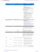
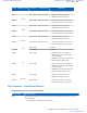
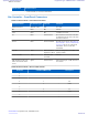
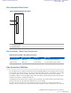

Table Of Contents
- 5827 Exhibit D - User Information
- Tune-Up Procedure
- User Manual
- MANUAL COVER PAGE
- Copyrights
- CMM Labeling and Disclosure Table
- Service Information
- Document History
- Contents
- List of Figures
- List of Tables
- List of Processes
- List of Procedures
- About MTS LiTE, MTS 2 and MTS 4 Installation, Configuration and Basic Service Manual
- MTS Overview
- General Safety
- Radio Frequency Distribution System
- RFDS Theory of Operation
- MTS LiTE and MTS 2 RFDS
- MTS 4 RFDS
- Expansion Cabinet RFDS
- Site Controller
- XHUB Controller
- Base Radio
- Power Supply Unit
- Cooling Fans
- Technical Specifications
- Environmental and Standards Specifications
- Cabinet and Module Specifications
- MTS Cabinets Frequency Range
- Dimensions of the MTS Cabinets
- RF Specifications
- Transmitter Specifications
- Receiver Specifications
- Site Controller Specifications
- Internal GPS Module Input Specifications
- MTS LiTE / MTS 2 Duplexer Specifications
- MTS LiTE / MTS 2 Preselector Specifications
- MTS 4 Duplexer Specifications
- MTS 4 Post Filter Specifications
- MTS 4 Preselector Specifications
- Auto Tune Cavity Combiner (ATCC) Specifications
- Manual Tune Cavity Combiner (MTCC) Specifications
- Hybrid Combiner Specifications
- Base Radio Specifications
- Power Supply Unit Specifications
- XHUB Controller Specifications
- RX Splitter Specifications
- MTS LiTE, MTS 2, and MTS 4 Connectors
- Expansion Options
- MTS 4 Outdoor Enclosure
- Appendix A: Field Replaceable Units (FRUs)
- Appendix B: Planned Maintenance Inspection (PMI)
- Appendix C: Static Precautions and ESD Strap
- Appendix D: TETRA/Dimetra Acronyms

Site Controller Rear Panel
Figure 168: Site Controller Rear Panel
2
1
1 — X21/Remote GPS
2 — Alarms/Control
Site Controller – Rear Panel Connectors
Table 79: Site Controller - Rear Panel Connectors
Connector Name Connector Type To/From Comment
Remote GPS/ X.21 IDE 26pin Junction Panel Connects to remote GPS/ X.21
Alarms/Control IDE 34pin Junction Panel Provides Alarm/Control interface
Site Controller CAN Bus
The CAN Bus provides a common communication bus between RFDS equipment, Power Supply Unit (PSU) and the
Site Controller. The CAN Bus connects to the Site Controller, PSU, DPM, and ATCC. The modules on the CAN Bus
are assigned an address for the CAN Bus. When there are more than one modules of the same type, assigned a
functionality in MTS to each node. Mapping between the track number, CAN ID, and function relies on the fact that
the unique track number is available from each unit.
At initialization of the MTS, the factory configures the Site Controller with a relation between track number and the
function of the node. You can modify this configuration in a service situation.
If a node is removed or is defective, the Site Controller knows the track number of a non-responding FRU and
therefore it can make a proper service report which tells exactly what FRU to replace. When the service is carried out,
Site Controller | 271
6802800U74-AD | September 2014 | Send Feedback
Applicant: Motorola Solutions
Equipment Type: ABZ89FC5827 / 109AB-5827
Exhibit D2