
User's Manual


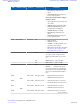
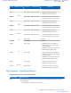
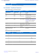
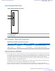

Table Of Contents
- 5827 Exhibit D - User Information
- Tune-Up Procedure
- User Manual
- MANUAL COVER PAGE
- Copyrights
- CMM Labeling and Disclosure Table
- Service Information
- Document History
- Contents
- List of Figures
- List of Tables
- List of Processes
- List of Procedures
- About MTS LiTE, MTS 2 and MTS 4 Installation, Configuration and Basic Service Manual
- MTS Overview
- General Safety
- Radio Frequency Distribution System
- RFDS Theory of Operation
- MTS LiTE and MTS 2 RFDS
- MTS 4 RFDS
- Expansion Cabinet RFDS
- Site Controller
- XHUB Controller
- Base Radio
- Power Supply Unit
- Cooling Fans
- Technical Specifications
- Environmental and Standards Specifications
- Cabinet and Module Specifications
- MTS Cabinets Frequency Range
- Dimensions of the MTS Cabinets
- RF Specifications
- Transmitter Specifications
- Receiver Specifications
- Site Controller Specifications
- Internal GPS Module Input Specifications
- MTS LiTE / MTS 2 Duplexer Specifications
- MTS LiTE / MTS 2 Preselector Specifications
- MTS 4 Duplexer Specifications
- MTS 4 Post Filter Specifications
- MTS 4 Preselector Specifications
- Auto Tune Cavity Combiner (ATCC) Specifications
- Manual Tune Cavity Combiner (MTCC) Specifications
- Hybrid Combiner Specifications
- Base Radio Specifications
- Power Supply Unit Specifications
- XHUB Controller Specifications
- RX Splitter Specifications
- MTS LiTE, MTS 2, and MTS 4 Connectors
- Expansion Options
- MTS 4 Outdoor Enclosure
- Appendix A: Field Replaceable Units (FRUs)
- Appendix B: Planned Maintenance Inspection (PMI)
- Appendix C: Static Precautions and ESD Strap
- Appendix D: TETRA/Dimetra Acronyms

Switch Name Switch Function
• Push and hold (>3 seconds) for Hard Reset.
Site Controller – Front Panel Connectors
Table 77: Site Controller - Front Panel Connectors
Connector Name Connector Type To/From Comment
POWER SUPPLY MOLEX (2 Pin) PSU 28.5 VDC
BR RJ45 BR Ethernet
CAN RJ45 BR CAN Bus connection
E1 RJ45 Junction Panel Pin connections on the Site Controller
are different from the ones on the Junc-
tion Panel connector.
Service RJ45 Service Terminal Provides service access. See Table 78:
Site Controller - Service Cable Pinouts
on page 270 for service cable pinout
information. (Service Cable PN:
3066565B)
Exp.Cab. RJ45 XHUB in MTS 4
Expansion Cabinet
Only in configurations with MTS 4 Ex-
pansion Cabinet
Red In / Red Out RJ45 Redundant Site
Controller
Ethernet
GPS Antenna (for Site Con-
troller with internal GPS re-
ceiver)
QMA Junction Panel GPS antenna input. +5VDC bias for ac-
tive antenna.
Table 78: Site Controller - Service Cable Pinouts
RJ45 PIN D-SUB 9 FEMALE PIN Description
1
2
3
4 3 Rx
5 5 GND
6
7 2 Tx
8 5 GND
9
270 | Site Controller
Send Feedback | September 2014 | 6802800U74-AD
Applicant: Motorola Solutions
Equipment Type: ABZ89FC5827 / 109AB-5827
Exhibit D2