
User's Manual


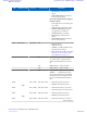
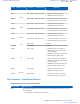
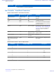
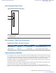

Table Of Contents
- 5827 Exhibit D - User Information
- Tune-Up Procedure
- User Manual
- MANUAL COVER PAGE
- Copyrights
- CMM Labeling and Disclosure Table
- Service Information
- Document History
- Contents
- List of Figures
- List of Tables
- List of Processes
- List of Procedures
- About MTS LiTE, MTS 2 and MTS 4 Installation, Configuration and Basic Service Manual
- MTS Overview
- General Safety
- Radio Frequency Distribution System
- RFDS Theory of Operation
- MTS LiTE and MTS 2 RFDS
- MTS 4 RFDS
- Expansion Cabinet RFDS
- Site Controller
- XHUB Controller
- Base Radio
- Power Supply Unit
- Cooling Fans
- Technical Specifications
- Environmental and Standards Specifications
- Cabinet and Module Specifications
- MTS Cabinets Frequency Range
- Dimensions of the MTS Cabinets
- RF Specifications
- Transmitter Specifications
- Receiver Specifications
- Site Controller Specifications
- Internal GPS Module Input Specifications
- MTS LiTE / MTS 2 Duplexer Specifications
- MTS LiTE / MTS 2 Preselector Specifications
- MTS 4 Duplexer Specifications
- MTS 4 Post Filter Specifications
- MTS 4 Preselector Specifications
- Auto Tune Cavity Combiner (ATCC) Specifications
- Manual Tune Cavity Combiner (MTCC) Specifications
- Hybrid Combiner Specifications
- Base Radio Specifications
- Power Supply Unit Specifications
- XHUB Controller Specifications
- RX Splitter Specifications
- MTS LiTE, MTS 2, and MTS 4 Connectors
- Expansion Options
- MTS 4 Outdoor Enclosure
- Appendix A: Field Replaceable Units (FRUs)
- Appendix B: Planned Maintenance Inspection (PMI)
- Appendix C: Static Precautions and ESD Strap
- Appendix D: TETRA/Dimetra Acronyms

LED LED/Port Name Position Controlled by Indication
• YELLOW: Ethernet activity present.
LED9
BR3
Port 3 LED1 HW, Enet switch
• OFF: Ethernet link not present.
• GREEN: Ethernet link present.
LED10 Port 3 LED2 HW, Enet switch
•
OFF: Ethernet activity not present.
• YELLOW: Ethernet activity present.
LED11
BR4
Port 4 LED1 HW, Enet switch
• OFF: Ethernet link not present.
• GREEN: Ethernet link present.
LED12 Port 4 LED2 HW, Enet switch
• OFF: Ethernet activity not present.
• YELLOW: Ethernet activity present.
LED13
Service
Port 5 LED1 HW, Enet switch
• OFF: Ethernet link not present.
• GREEN: Ethernet link present.
LED14 Port 5 LED2 HW, Enet switch
• OFF: Ethernet activity not present.
• YELLOW: Ethernet activity present.
CAN
Port 6 LED1 Not used.
Port 6 LED2 Not used.
LED15
E1
Port 7 LED1
• OFF: Primary E1 not configured.
• GREEN: Primary E1 OK (no LOS
(Loss Of Signal)).
• AMBER: Errors FE, CRC, BPV, PD.
• RED: Primary E1 failure LOS.
LED16 Port 7 LED2
• OFF: Secondary E1 not configured.
• GREEN: Secondary E1 OK (no LOS
(Loss Of Signal)).
• AMBER: Errors FE, CRC, BPV, PD.
• RED: Secondary E1 failure LOS.
LED17
Exp.Cab.
Port 8 LED1
• OFF: Ethernet link not present.
• GREEN: Ethernet link present.
LED18 Port 8 LED2
• OFF: Ethernet activity not present.
• YELLOW: Ethernet activity present.
Site Controller – Front Panel Switches
Table 76: Site Controller - Front Panel Switches
Switch Name Switch Function
Reset The front-panel switch can be used to either generate an interrupt to the processor or to ini-
tiate a Hard Reset.
• Push and hold (1 second) to generate interrupt.
Site Controller |
269
6802800U74-AD | September 2014 |
Send Feedback
Applicant: Motorola Solutions
Equipment Type: ABZ89FC5827 / 109AB-5827
Exhibit D2