
User's Manual


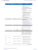
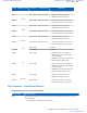
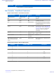
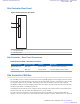

Table Of Contents
- 5827 Exhibit D - User Information
- Tune-Up Procedure
- User Manual
- MANUAL COVER PAGE
- Copyrights
- CMM Labeling and Disclosure Table
- Service Information
- Document History
- Contents
- List of Figures
- List of Tables
- List of Processes
- List of Procedures
- About MTS LiTE, MTS 2 and MTS 4 Installation, Configuration and Basic Service Manual
- MTS Overview
- General Safety
- Radio Frequency Distribution System
- RFDS Theory of Operation
- MTS LiTE and MTS 2 RFDS
- MTS 4 RFDS
- Expansion Cabinet RFDS
- Site Controller
- XHUB Controller
- Base Radio
- Power Supply Unit
- Cooling Fans
- Technical Specifications
- Environmental and Standards Specifications
- Cabinet and Module Specifications
- MTS Cabinets Frequency Range
- Dimensions of the MTS Cabinets
- RF Specifications
- Transmitter Specifications
- Receiver Specifications
- Site Controller Specifications
- Internal GPS Module Input Specifications
- MTS LiTE / MTS 2 Duplexer Specifications
- MTS LiTE / MTS 2 Preselector Specifications
- MTS 4 Duplexer Specifications
- MTS 4 Post Filter Specifications
- MTS 4 Preselector Specifications
- Auto Tune Cavity Combiner (ATCC) Specifications
- Manual Tune Cavity Combiner (MTCC) Specifications
- Hybrid Combiner Specifications
- Base Radio Specifications
- Power Supply Unit Specifications
- XHUB Controller Specifications
- RX Splitter Specifications
- MTS LiTE, MTS 2, and MTS 4 Connectors
- Expansion Options
- MTS 4 Outdoor Enclosure
- Appendix A: Field Replaceable Units (FRUs)
- Appendix B: Planned Maintenance Inspection (PMI)
- Appendix C: Static Precautions and ESD Strap
- Appendix D: TETRA/Dimetra Acronyms

LED LED/Port Name Position Controlled by Indication
• RED Blinking: Calibration is re-
quired.
• GREEN/RED Blinking: Frequency
lock is required, pull in.
Forced Non-Synchronized Configura-
tion (FNC) Mode:
•
OFF: Application is not running, free
run or NTP.
• GREEN: BTS synchronized to GPS.
• GREEN/AMBER Blinking: BTS
synchronized to a standby SC.
• AMBER Blinking: In training.
• RED Blinking: Calibration is re-
quired.
• GREEN/RED Blinking: Frequency
lock is required, pull in.
LED4 BTS Alarm Front Panel SW
• OFF: No alarms.
• GREEN: Not used.
• AMBER: CAN Bus problems, Exter-
nal alarms (minor Alarm)
• RED: Major/critical alarm, for details
see Table 92: Site Controller LED
Fault Indications on page 311
SW 3 LEDs blinking together: R (red) RRR-
>Y (yellow) YYY->G (green) GGG –
LED test just after BTS reset or power
up
SW RRRR blinking – replace the FRU
SW RRR blinking – replace the FRU
SW R->RR->RRR->RRRR->R->RR->RRR-
>RRRR-> ... – initializing file system
(do not turn off and wait a few minutes,
then application and configuration will
have to be downloaded after initializa-
tion).
LED5
BR1
Port 1 LED1 HW, Enet switch
• OFF: Ethernet link not present.
• GREEN: Ethernet link present.
LED6 Port 1 LED2 HW, Enet switch
• OFF: Ethernet activity not present.
• YELLOW: Ethernet activity present.
LED7
BR2
Port 2 LED1 HW, Enet switch
• OFF: Ethernet link not present.
• GREEN: Ethernet link present.
LED8 Port 2 LED2 HW, Enet switch
• OFF: Ethernet activity not present.
Table continued…
268 | Site Controller
Send Feedback | September 2014 | 6802800U74-AD
Applicant: Motorola Solutions
Equipment Type: ABZ89FC5827 / 109AB-5827
Exhibit D2