
User's Manual


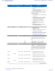
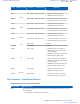
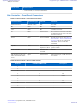
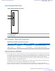

Table Of Contents
- 5827 Exhibit D - User Information
- Tune-Up Procedure
- User Manual
- MANUAL COVER PAGE
- Copyrights
- CMM Labeling and Disclosure Table
- Service Information
- Document History
- Contents
- List of Figures
- List of Tables
- List of Processes
- List of Procedures
- About MTS LiTE, MTS 2 and MTS 4 Installation, Configuration and Basic Service Manual
- MTS Overview
- General Safety
- Radio Frequency Distribution System
- RFDS Theory of Operation
- MTS LiTE and MTS 2 RFDS
- MTS 4 RFDS
- Expansion Cabinet RFDS
- Site Controller
- XHUB Controller
- Base Radio
- Power Supply Unit
- Cooling Fans
- Technical Specifications
- Environmental and Standards Specifications
- Cabinet and Module Specifications
- MTS Cabinets Frequency Range
- Dimensions of the MTS Cabinets
- RF Specifications
- Transmitter Specifications
- Receiver Specifications
- Site Controller Specifications
- Internal GPS Module Input Specifications
- MTS LiTE / MTS 2 Duplexer Specifications
- MTS LiTE / MTS 2 Preselector Specifications
- MTS 4 Duplexer Specifications
- MTS 4 Post Filter Specifications
- MTS 4 Preselector Specifications
- Auto Tune Cavity Combiner (ATCC) Specifications
- Manual Tune Cavity Combiner (MTCC) Specifications
- Hybrid Combiner Specifications
- Base Radio Specifications
- Power Supply Unit Specifications
- XHUB Controller Specifications
- RX Splitter Specifications
- MTS LiTE, MTS 2, and MTS 4 Connectors
- Expansion Options
- MTS 4 Outdoor Enclosure
- Appendix A: Field Replaceable Units (FRUs)
- Appendix B: Planned Maintenance Inspection (PMI)
- Appendix C: Static Precautions and ESD Strap
- Appendix D: TETRA/Dimetra Acronyms

Site Controller – Front Panel Indicators (LED)
Figure 167: Site Controller - Front Panel LEDs Position
BR1
LED12
LED11
BR2
CAN
Service
BR3
BR4
E1
Exp. Cab.
LED8
LED7
LED16
LED15
Not used
LED18
LED17
LED14
LED13
LED6
LED5
LED10
LED9
Table 75: Site Controller - Front Panel Indicators (LED)
LED LED/Port Name Position Controlled by Indication
LED1 Active Front Panel SW Site Controller is active or standby:
• OFF: Site Controller main applica-
tion not running.
• GREEN: E1/X.21 relay energized.
•
AMBER: E1/X.21 relay not ener-
gized.
• RED: Failed Site Controller, replace
FRU.
LED2 Mode
Front Panel SW
Trunking status:
• OFF: Boot up/No trunking/Standby.
• GREEN: Wide area trunking.
• AMBER: Local site trunking.
LED3 GPS Front Panel SW
Automatic Synchronized Configura-
tion (ASC) Mode:
• OFF: Application is not running.
• GREEN: BTS synchronized to GPS.
• GREEN/AMBER Blinking: BTS
synchronized to a standby SC.
• AMBER Blinking: In training.
• AMBER: GPS Free run mode
synchronized (ETSI spec).
• RED: NTP, NTP malfunction.
Table continued…
Site Controller | 267
6802800U74-AD | September 2014 | Send Feedback
Applicant: Motorola Solutions
Equipment Type: ABZ89FC5827 / 109AB-5827
Exhibit D2