
User's Manual


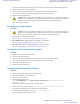


Table Of Contents
- 5827 Exhibit D - User Information
- Tune-Up Procedure
- User Manual
- MANUAL COVER PAGE
- Copyrights
- CMM Labeling and Disclosure Table
- Service Information
- Document History
- Contents
- List of Figures
- List of Tables
- List of Processes
- List of Procedures
- About MTS LiTE, MTS 2 and MTS 4 Installation, Configuration and Basic Service Manual
- MTS Overview
- General Safety
- Radio Frequency Distribution System
- RFDS Theory of Operation
- MTS LiTE and MTS 2 RFDS
- MTS 4 RFDS
- Expansion Cabinet RFDS
- Site Controller
- XHUB Controller
- Base Radio
- Power Supply Unit
- Cooling Fans
- Technical Specifications
- Environmental and Standards Specifications
- Cabinet and Module Specifications
- MTS Cabinets Frequency Range
- Dimensions of the MTS Cabinets
- RF Specifications
- Transmitter Specifications
- Receiver Specifications
- Site Controller Specifications
- Internal GPS Module Input Specifications
- MTS LiTE / MTS 2 Duplexer Specifications
- MTS LiTE / MTS 2 Preselector Specifications
- MTS 4 Duplexer Specifications
- MTS 4 Post Filter Specifications
- MTS 4 Preselector Specifications
- Auto Tune Cavity Combiner (ATCC) Specifications
- Manual Tune Cavity Combiner (MTCC) Specifications
- Hybrid Combiner Specifications
- Base Radio Specifications
- Power Supply Unit Specifications
- XHUB Controller Specifications
- RX Splitter Specifications
- MTS LiTE, MTS 2, and MTS 4 Connectors
- Expansion Options
- MTS 4 Outdoor Enclosure
- Appendix A: Field Replaceable Units (FRUs)
- Appendix B: Planned Maintenance Inspection (PMI)
- Appendix C: Static Precautions and ESD Strap
- Appendix D: TETRA/Dimetra Acronyms

Table 74: MTS 4 Expansion Cabinet RF Configurations
RF Configuration
Max Power (W)
Cavity Combin-
er
RX Splitter
Low Pwr High Pwr
1 – 2 BRs
TX/RX on 2 ant. 10 25 1 2
TX/RX on 2 ant., RX
on 1 ant.
10 25 1 3
TX on 2 ant., RX on 2
ant.
10 25 1 2
TX on 2 ant., RX on 3
ant.
10 25 1 3
TX/RX on 1 ant., RX
on 1 ant
8 20 1 + phasing har-
ness
2
TX/RX on 1 ant., RX
on 2 ant.
8 20 1 + phasing har-
ness
3
TX on 1 ant., RX on 2
ant.
10 20 1 + phasing har-
ness
2
TX on 1 ant., RX on 3
ant.
10 20 1 + phasing har-
ness
3
3 – 4 BRs
TX/RX on 2 ant. 10 25 2 (comb) 2
TX/RX on 2 ant., RX
on 1 ant.
10 25 2 (comb) 3
TX on 2 ant., RX on 2
ant.
10 25 2 (comb) 2
TX on 2 ant., RX on 3
ant.
10 25 2 (comb) 3
TX/RX on 1 ant., RX
on 1 ant.
8 20 2 (comb) + phas-
ing harness
2
TX/RX on 1 ant., RX
on 2 ant.
8 20 2 (comb) + phas-
ing harness
3
TX on 1 ant., RX on 2
ant.
8 20 2 (comb) + phas-
ing harness
2
TX on 1 ant., RX on 3
ant.
8 20 2 (comb) + phas-
ing harness
3
Note: For 260 MHz version of MTS there are no phasing harness configurations, so please disregard from
these in Table 74: MTS 4 Expansion Cabinet RF Configurations on page 258.
258
| Radio Frequency Distribution System
Send Feedback | September 2014 | 6802800U74-AD
Applicant: Motorola Solutions
Equipment Type: ABZ89FC5827 / 109AB-5827
Exhibit D2