
User's Manual


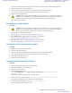

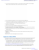


Table Of Contents
- 5827 Exhibit D - User Information
- Tune-Up Procedure
- User Manual
- MANUAL COVER PAGE
- Copyrights
- CMM Labeling and Disclosure Table
- Service Information
- Document History
- Contents
- List of Figures
- List of Tables
- List of Processes
- List of Procedures
- About MTS LiTE, MTS 2 and MTS 4 Installation, Configuration and Basic Service Manual
- MTS Overview
- General Safety
- Radio Frequency Distribution System
- RFDS Theory of Operation
- MTS LiTE and MTS 2 RFDS
- MTS 4 RFDS
- Expansion Cabinet RFDS
- Site Controller
- XHUB Controller
- Base Radio
- Power Supply Unit
- Cooling Fans
- Technical Specifications
- Environmental and Standards Specifications
- Cabinet and Module Specifications
- MTS Cabinets Frequency Range
- Dimensions of the MTS Cabinets
- RF Specifications
- Transmitter Specifications
- Receiver Specifications
- Site Controller Specifications
- Internal GPS Module Input Specifications
- MTS LiTE / MTS 2 Duplexer Specifications
- MTS LiTE / MTS 2 Preselector Specifications
- MTS 4 Duplexer Specifications
- MTS 4 Post Filter Specifications
- MTS 4 Preselector Specifications
- Auto Tune Cavity Combiner (ATCC) Specifications
- Manual Tune Cavity Combiner (MTCC) Specifications
- Hybrid Combiner Specifications
- Base Radio Specifications
- Power Supply Unit Specifications
- XHUB Controller Specifications
- RX Splitter Specifications
- MTS LiTE, MTS 2, and MTS 4 Connectors
- Expansion Options
- MTS 4 Outdoor Enclosure
- Appendix A: Field Replaceable Units (FRUs)
- Appendix B: Planned Maintenance Inspection (PMI)
- Appendix C: Static Precautions and ESD Strap
- Appendix D: TETRA/Dimetra Acronyms

Updating the Mapping List with the New TrackID
Procedure:
1 Log on to the Site Controller.
2 View the mapping list by entering: can check_mapping.
Step example:
Units are present:
Device Track ID
DPM 1 JTH0500101
DPM 2 JTH0500105
PSU 1 JTH0500200
Units are not present:
ATCC 1 JTH0500201
Track ID not mapped:
JTH0500102
3 On the mapping list, locate the removed unit indicated as Units are not present.
4 Delete the old CAN Bus unit from the CAN Bus unit mapping list by entering: can remove_mapping
attc<X>.
<X> identifies the new unit name and is a digit between 0 and 2.
Step example: can remove_mapping atcc 1
5 Add the new CAN Bus unit to the CAN Bus unit mapping list by entering: add_mapping attc<X><track
ID>.
<track ID> is a Track ID of the new unit.
<X> identifies the new unit name and is a digit between 0 and 2.
Note: The new unit Track ID is present on the replaced unit label as Track ID not mapped.
Step example: can add_mapping atcc 1 JTH0500102
6 View the updated mapping list by entering: can check_mapping.
7 On the mapping list, check that there are no units labeled as Track ID not mapped or Units are not
present.
Tuning the MTCC in a BTS in Tetra Application Mode
The Manually Tuned Cavity Combiner (MTCC) can have 2 or 4 inputs. The TX output of each BR is connected to an
input on the MTCC. The output of the MTCC is connected to the Antenna Port of the BTS via the TX-path of a
duplex filter. A configuration file has been uploaded to the Site Controller, defining the TX frequencies of all the
BRs.
Equipment: High Power Power Meter (PM) like Stabilock 4032, which can handle up to 120W. Service computer.
Procedure:
1 Calibrate the PM and set the frequency to the center frequency of the duplex filter. Set the PM to display Watts.
2 Connect the PM to the TX antenna connector of the BTS.
256 | Radio Frequency Distribution System
Send Feedback | September 2014 | 6802800U74-AD
Applicant: Motorola Solutions
Equipment Type: ABZ89FC5827 / 109AB-5827
Exhibit D2