
User's Manual


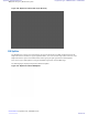

Table Of Contents
- 5827 Exhibit D - User Information
- Tune-Up Procedure
- User Manual
- MANUAL COVER PAGE
- Copyrights
- CMM Labeling and Disclosure Table
- Service Information
- Document History
- Contents
- List of Figures
- List of Tables
- List of Processes
- List of Procedures
- About MTS LiTE, MTS 2 and MTS 4 Installation, Configuration and Basic Service Manual
- MTS Overview
- General Safety
- Radio Frequency Distribution System
- RFDS Theory of Operation
- MTS LiTE and MTS 2 RFDS
- MTS 4 RFDS
- Expansion Cabinet RFDS
- Site Controller
- XHUB Controller
- Base Radio
- Power Supply Unit
- Cooling Fans
- Technical Specifications
- Environmental and Standards Specifications
- Cabinet and Module Specifications
- MTS Cabinets Frequency Range
- Dimensions of the MTS Cabinets
- RF Specifications
- Transmitter Specifications
- Receiver Specifications
- Site Controller Specifications
- Internal GPS Module Input Specifications
- MTS LiTE / MTS 2 Duplexer Specifications
- MTS LiTE / MTS 2 Preselector Specifications
- MTS 4 Duplexer Specifications
- MTS 4 Post Filter Specifications
- MTS 4 Preselector Specifications
- Auto Tune Cavity Combiner (ATCC) Specifications
- Manual Tune Cavity Combiner (MTCC) Specifications
- Hybrid Combiner Specifications
- Base Radio Specifications
- Power Supply Unit Specifications
- XHUB Controller Specifications
- RX Splitter Specifications
- MTS LiTE, MTS 2, and MTS 4 Connectors
- Expansion Options
- MTS 4 Outdoor Enclosure
- Appendix A: Field Replaceable Units (FRUs)
- Appendix B: Planned Maintenance Inspection (PMI)
- Appendix C: Static Precautions and ESD Strap
- Appendix D: TETRA/Dimetra Acronyms

3 On the mapping list, locate the removed unit indicated as Units are not present.
4 Delete the old CAN Bus unit from the CAN Bus unit mapping list by entering: can remove_mapping <X>.
<X> identifies the old unit name and is digit between 0 and 3.
Step example: can remove_mapping dpm 2.
5 Add the new CAN Bus unit to the CAN Bus unit mapping list by entering: add_mapping dpm<X><track
ID>.
<track ID> is a Track ID of the new unit.
<X> identifies the new unit name and is a digit between 0 and 3.
Note: The new unit Track ID is present on the replaced unit label and indicated as Track ID not
mapped.
Step example: can add_mapping dpm 2 JTH0500102
6 View the updated mapping list by entering: can check_mapping.
7 On the mapping list, check that there are no units labeled as Track ID not mapped or Units are not
present.
Cavity Combiner
Note: MTS 2 does not support Cavity Combiners.
There are two types of Cavity Combiners available:
• Auto Tune Cavity Combiners (ATCC)
• Manual Tune Cavity Combiners (MTCC)
MTCCs are functionally the same as ATCCs except that they are tuned manually instead of electronically.
Note: 260 MHz configurations does not support MTCC.
Minimum channel spacing of the TX channels is 150 kHz while the recommended channel spacing is 250 kHz. This
limitation applies to all Cavity Combiners in all cabinets connected to the same transmit antenna.
Figure 157: Auto Tune Cavity Combiner
Radio Frequency Distribution System | 253
6802800U74-AD | September 2014 | Send Feedback
Applicant: Motorola Solutions
Equipment Type: ABZ89FC5827 / 109AB-5827
Exhibit D2