
User's Manual
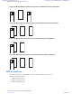


Table Of Contents
- 5827 Exhibit D - User Information
- Tune-Up Procedure
- User Manual
- MANUAL COVER PAGE
- Copyrights
- CMM Labeling and Disclosure Table
- Service Information
- Document History
- Contents
- List of Figures
- List of Tables
- List of Processes
- List of Procedures
- About MTS LiTE, MTS 2 and MTS 4 Installation, Configuration and Basic Service Manual
- MTS Overview
- General Safety
- Radio Frequency Distribution System
- RFDS Theory of Operation
- MTS LiTE and MTS 2 RFDS
- MTS 4 RFDS
- Expansion Cabinet RFDS
- Site Controller
- XHUB Controller
- Base Radio
- Power Supply Unit
- Cooling Fans
- Technical Specifications
- Environmental and Standards Specifications
- Cabinet and Module Specifications
- MTS Cabinets Frequency Range
- Dimensions of the MTS Cabinets
- RF Specifications
- Transmitter Specifications
- Receiver Specifications
- Site Controller Specifications
- Internal GPS Module Input Specifications
- MTS LiTE / MTS 2 Duplexer Specifications
- MTS LiTE / MTS 2 Preselector Specifications
- MTS 4 Duplexer Specifications
- MTS 4 Post Filter Specifications
- MTS 4 Preselector Specifications
- Auto Tune Cavity Combiner (ATCC) Specifications
- Manual Tune Cavity Combiner (MTCC) Specifications
- Hybrid Combiner Specifications
- Base Radio Specifications
- Power Supply Unit Specifications
- XHUB Controller Specifications
- RX Splitter Specifications
- MTS LiTE, MTS 2, and MTS 4 Connectors
- Expansion Options
- MTS 4 Outdoor Enclosure
- Appendix A: Field Replaceable Units (FRUs)
- Appendix B: Planned Maintenance Inspection (PMI)
- Appendix C: Static Precautions and ESD Strap
- Appendix D: TETRA/Dimetra Acronyms

Replacing the MTS 4 Duplexer
Process:
1 Remove the Duplexer.
See Removing the MTS 4 Duplexer on page 249.
2 Insert the Duplexer into the filter tray.
See
Inserting the MTS 4 Duplexer into the Cabinet on page 249.
3 Update the mapping list with the new unit TrackID.
See Updating the Mapping List with the New Unit TrackID on page 249.
Removing the MTS 4 Duplexer
Procedure:
1
Warning: RF energy hazard and potential equipment damage precaution.
To prevent accidental contact with high energy and injury to personnel, switch ff all power to the Power Supply
Unit.
2 Remove the four screws holding the front panel.
3 Loosen the two screws holding the front section of the top panel and slide off the panel.
4 Loosen the screws fastening the rear section of the top panel and slide off the panel.
5 Unscrew the antenna cable and remove the RX, TX and signal cables.
6 Loosen the two fastening screws at the front enough to free the mounting bracket.
7 Slide the Duplexer out of the cabinet.
8 Remove the Duplexer from the bracket and replace.
Reinstalling the MTS 4 Duplexer
Procedure:
1 Insert the Duplexer into the cabinet
.
See Inserting the MTS 4 Duplexer into the Cabinet on page 249.
2 Update the mapping list with the new unit TrackID.
See Updating the Mapping List with the New Unit TrackID on page 249.
Inserting the MTS 4 Duplexer into the Cabinet
Procedure:
1 Fasten the Duplexer onto the bracket with screws.
2 Slide the Duplexer into the cabinet.
3 Tighten the two fastening screws at the front to secure the mounting bracket
4 Attach the antenna cable and the RX, TX and signal cables.
5 Slide on the top rear and front panels and fasten these with screws.
6 Put the front panel back on and screw this into place.
7 Put the door of the cabinet back on.
Updating the Mapping List with the New Unit TrackID
Procedure:
1 Log on to the Site Controller.
Radio Frequency Distribution System | 249
6802800U74-AD | September 2014 |
Send Feedback
Applicant: Motorola Solutions
Equipment Type: ABZ89FC5827 / 109AB-5827
Exhibit D2