
User's Manual
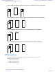


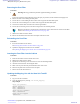
Table Of Contents
- 5827 Exhibit D - User Information
- Tune-Up Procedure
- User Manual
- MANUAL COVER PAGE
- Copyrights
- CMM Labeling and Disclosure Table
- Service Information
- Document History
- Contents
- List of Figures
- List of Tables
- List of Processes
- List of Procedures
- About MTS LiTE, MTS 2 and MTS 4 Installation, Configuration and Basic Service Manual
- MTS Overview
- General Safety
- Radio Frequency Distribution System
- RFDS Theory of Operation
- MTS LiTE and MTS 2 RFDS
- MTS 4 RFDS
- Expansion Cabinet RFDS
- Site Controller
- XHUB Controller
- Base Radio
- Power Supply Unit
- Cooling Fans
- Technical Specifications
- Environmental and Standards Specifications
- Cabinet and Module Specifications
- MTS Cabinets Frequency Range
- Dimensions of the MTS Cabinets
- RF Specifications
- Transmitter Specifications
- Receiver Specifications
- Site Controller Specifications
- Internal GPS Module Input Specifications
- MTS LiTE / MTS 2 Duplexer Specifications
- MTS LiTE / MTS 2 Preselector Specifications
- MTS 4 Duplexer Specifications
- MTS 4 Post Filter Specifications
- MTS 4 Preselector Specifications
- Auto Tune Cavity Combiner (ATCC) Specifications
- Manual Tune Cavity Combiner (MTCC) Specifications
- Hybrid Combiner Specifications
- Base Radio Specifications
- Power Supply Unit Specifications
- XHUB Controller Specifications
- RX Splitter Specifications
- MTS LiTE, MTS 2, and MTS 4 Connectors
- Expansion Options
- MTS 4 Outdoor Enclosure
- Appendix A: Field Replaceable Units (FRUs)
- Appendix B: Planned Maintenance Inspection (PMI)
- Appendix C: Static Precautions and ESD Strap
- Appendix D: TETRA/Dimetra Acronyms

Reinstalling the MTS 4 Preselector
Procedure:
1 Fasten the Preselector onto the bracket.
2 Slide the Preselector into the cabinet.
3 Tighten the two fastening screws at the front.
4 Screw on the antenna cable and connect the RX cables to the back of the Preselector.
5 Slide on the top rear and front panels and fasten these with screws.
6 Put the front panel back on and screw this into place.
7 Put the door of the cabinet back on.
MTS 4 Duplexer
The Duplexer is a Preselector with an integrated receiver multicoupler (RMC) and a Post Filter with a digital power
monitor (DPM) combined into one unit. These form the two bandpass filters that make up the Duplexer; one is a
receive filter and the other a transmit filter. See the block schematic of the MTS 4 Duplexer in Figure 154: Schematic
Diagram of MTS 4 Duplexer on page 248
For 400 MHz, the duplex spacing between a transmitter frequency and the corresponding receive frequency is 10
MHz, with the transmitter frequency highest. This leaves a 5 MHz spacing between the lowest possible transmit
frequency and the highest possible receive frequency.
For 260 MHz, the duplex spacing between a transmit frequency and the corresponding receive frequency is 9 MHz,
and leaves a 3 MHz spacing between the lowest possible transmit frequency and the highest possible receive
frequency.
For 800 MHz, the duplex spacing between a transmit frequency and the corresponding receive frequency is 45 MHz,
and leaves a 19 MHz spacing between the lowest possible transmit frequency and the highest possible receive
frequency.
The MTS 4 Duplexer has 4 RX outputs and one expansion output. It can handle a maximum power 180 Watts.
Radio Frequency Distribution System
| 247
6802800U74-AD | September 2014 |
Send Feedback
Applicant: Motorola Solutions
Equipment Type: ABZ89FC5827 / 109AB-5827
Exhibit D2