
User's Manual
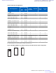
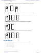
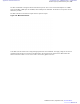


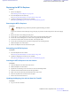

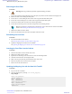
Table Of Contents
- 5827 Exhibit D - User Information
- Tune-Up Procedure
- User Manual
- MANUAL COVER PAGE
- Copyrights
- CMM Labeling and Disclosure Table
- Service Information
- Document History
- Contents
- List of Figures
- List of Tables
- List of Processes
- List of Procedures
- About MTS LiTE, MTS 2 and MTS 4 Installation, Configuration and Basic Service Manual
- MTS Overview
- General Safety
- Radio Frequency Distribution System
- RFDS Theory of Operation
- MTS LiTE and MTS 2 RFDS
- MTS 4 RFDS
- Expansion Cabinet RFDS
- Site Controller
- XHUB Controller
- Base Radio
- Power Supply Unit
- Cooling Fans
- Technical Specifications
- Environmental and Standards Specifications
- Cabinet and Module Specifications
- MTS Cabinets Frequency Range
- Dimensions of the MTS Cabinets
- RF Specifications
- Transmitter Specifications
- Receiver Specifications
- Site Controller Specifications
- Internal GPS Module Input Specifications
- MTS LiTE / MTS 2 Duplexer Specifications
- MTS LiTE / MTS 2 Preselector Specifications
- MTS 4 Duplexer Specifications
- MTS 4 Post Filter Specifications
- MTS 4 Preselector Specifications
- Auto Tune Cavity Combiner (ATCC) Specifications
- Manual Tune Cavity Combiner (MTCC) Specifications
- Hybrid Combiner Specifications
- Base Radio Specifications
- Power Supply Unit Specifications
- XHUB Controller Specifications
- RX Splitter Specifications
- MTS LiTE, MTS 2, and MTS 4 Connectors
- Expansion Options
- MTS 4 Outdoor Enclosure
- Appendix A: Field Replaceable Units (FRUs)
- Appendix B: Planned Maintenance Inspection (PMI)
- Appendix C: Static Precautions and ESD Strap
- Appendix D: TETRA/Dimetra Acronyms

Table 73: MTS 4 RF Configurations
RF Configuration
Max Power [W]
Cavity
Combiner
Duplexer
Pre se-
lector
Post Fil-
ter
Low
Pwr
High
Pwr
1 - 2 BRs
TX/RX on 2 ant. 25 40 (20) - 2 - -
TX/RX on 2 ant., RX on 1 ant. 25 40 (20)
- 2 1 -
TX on 2 ant., RX on 2 ant. 25 40 (20) - - 2 2
TX on 2 ant., RX on 3 ant. 25 40 (20) - - 3 2
TX/RX on 1 ant., RX on 1 ant. 10 25 (10) 1 1 1 -
TX/RX on 1 ant., RX on 2 ant. 10 25 (10) 1 1 2 -
TX on 1 ant., RX on 2 ant. 10 25 (10) 1 - 2 1
TX on 1 ant., RX on 3 ant. 10 25 (10) 1 - 3 1
3 - 4 BRs
TX/RX on 2 ant. 10 25 (10) 2 2 - -
TX/RX on 2 ant., RX on 1 ant. 10 25 (10) 2 2 1 -
TX on 2 ant., RX on 2 ant. 10 25 (10) 2 - 2 2
TX on 2 ant., RX on 3 ant. 10 25 (10) 2 - 3 2
TX/RX on 1 ant., RX on 1 ant. 10 25 (10) 2 (comb) 1 1 -
TX/RX on 1 ant., RX on 2 ant. 10 25 (10) 2 (comb) 1 2 -
TX on 1 ant., RX on 2 ant. 10 25 (10) 2 (comb) - 2 1
TX on 1 ant., RX on 3 ant. 10 25 (10) 2 (comb) - 3 1
The following figures show the positions of filters in the filter tray.
Figure 146: MTS 4 TX/RX on one Antenna and up to two RX Antennas Filter Configuration
PRESELECTOR
DUPLEXER
CAN
IN
CAN
OUT
PRESELECTOR
Radio Frequency Distribution System | 243
6802800U74-AD | September 2014 | Send Feedback
Applicant: Motorola Solutions
Equipment Type: ABZ89FC5827 / 109AB-5827
Exhibit D2